
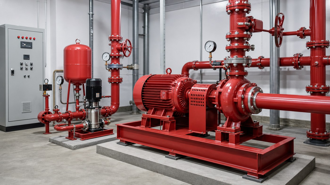
Sizing a vertical inline fire pump requires matching three critical parameters to your system: flow rate (GPM), total dynamic head (TDH in feet), and the fire protection standard your installation must meet. Start with the hydraulic demand from your fire protection engineer, then verify the pump curve delivers that flow at the required pressure, and finally confirm the motor, materials, and controls match the service conditions. This guide walks through the calculation method, field verification steps, and the common sizing errors that lead to failed inspections or underperforming systems.
Key Takeaways
- Fire pump sizing begins with the hydraulic calculation from your fire protection design, not the pump catalog.
- Total dynamic head includes static lift, friction loss at design flow, hose allowance, and the rated pressure at the most remote sprinkler or standpipe.
- The pump curve must show rated flow between 100% and 150% of churn (shutoff) pressure, with the motor sized to handle maximum demand without overload.
- Suction conditions, electrical supply, controller type, and installation clearances are non-negotiable; fire pumps operate under emergency conditions and cannot tolerate improvisation.
- Document everything: flow requirement, pressure target, elevation change, pipe schedule, power details, and the applicable fire code or insurance requirement.
Calculate Your Required Flow and Head
Your fire protection hydraulic calculation provides the design flow rate. Common ranges are 500-2500 GPM for building systems, though industrial or high-hazard occupancies may require more. The pressure requirement comes from the system demand curve: the sum of elevation change, pipe friction, fitting losses, and the minimum pressure at the hydraulically most remote sprinkler head.
Total Dynamic Head formula:
TDH = Static Height + Friction Loss + Pressure at Remote Point + Hose Stream Allowance
For example, if your remote sprinkler requires 50 PSI, the elevation change is 60 feet, friction loss at 1000 GPM is 35 feet, and you need 100 PSI hose stream allowance at a standpipe connection, your total demand is approximately:
TDH = 60 ft + 35 ft + (50 PSI × 2.31 ft/PSI) + (100 PSI × 2.31 ft/PSI) = 60 + 35 + 115.5 + 231 = 441.5 feet
Round up for safety margin. Your pump must deliver the design flow (1000 GPM in this example) at roughly 450 feet of head. Now compare this operating point to available pump performance curves.
Match the Pump Curve to Your Duty Point
Fire pump curves differ from standard centrifugal pump curves. They must show relatively flat performance from shutoff to 150% of rated flow, ensuring stable pressure across the range of demand. Place your calculated duty point (flow and head) on the curve. The pump should operate within its best efficiency zone at rated conditions, not at the extreme ends of its range.
Check these curve characteristics:
- Rated flow should fall between 100% and 140% of design demand to allow for future system modifications.
- Shutoff head (zero flow) should not exceed 140% of rated head to prevent overpressure during low-demand conditions.
- The curve must be smooth without dips or instability in the operating range.
- Net Positive Suction Head Required (NPSHR) at your flow must be less than available NPSH by at least 3-5 feet margin.
Verify Suction and Electrical Conditions
Vertical inline fire pumps typically mount on a suction riser from an underground tank or city main. If your source is a tank, measure from the minimum tank level to the pump centerline. If the source is a city connection, verify the minimum supply pressure during peak demand or simultaneous fire events. Inadequate suction causes cavitation, which destroys impellers and leads to rapid performance loss.
NPSH Available calculation for tank suction:
NPSHA = Atmospheric Pressure (in feet) + Static Suction Head – Friction Loss in Suction Pipe – Vapor Pressure of Water
At sea level and 60°F, atmospheric pressure is about 34 feet, and water vapor pressure is negligible. If your tank provides 15 feet of static head and suction friction is 3 feet, NPSHA = 34 + 15 – 3 = 46 feet. Compare this to the pump’s NPSHR at your flow rate.
Electrical requirements are strict. Fire pumps use dedicated feeders with no other loads, supervised disconnects, and emergency power transfer where required. Confirm your motor voltage matches the available supply (typically 460V three-phase for pumps above 50 HP), and verify the controller is listed for fire pump service. Standard motor starters are not acceptable.
Field Installation and Startup Verification
Installation mistakes cause more fire pump failures than incorrect sizing. The pump must be anchored to a concrete pad or structural support capable of handling operating loads and vibration. Align the pump and motor shafts within manufacturer tolerances—misalignment leads to bearing failure and seal leaks.
Pipe the suction and discharge with proper support every 10 feet of horizontal run and immediately adjacent to flanges. Do not allow pipe weight or thermal expansion to load the pump casing. Install a suction pressure gauge, discharge pressure gauge, and flow meter in accessible locations for testing and routine checks.
At startup, record these parameters:
- Suction pressure (should match calculated NPSHA)
- Discharge pressure at churn, rated flow, and 150% flow
- Motor current at each test point (should not exceed nameplate full-load amps)
- Vibration and noise levels (sudden increases indicate cavitation, misalignment, or debris)
- Flow rate using the installed flow meter or a calibrated pitot tube at the discharge
If discharge pressure at rated flow is more than 5% below the curve, check for impeller wear, wrong rotation direction, air entrainment, or internal recirculation. If motor current exceeds nameplate at any test point, the pump is oversized for the system or the impeller diameter is too large.
Common Sizing and Selection Errors
| Mistake | Consequence | Correction |
|---|---|---|
| Using residual city pressure instead of minimum supply pressure | Insufficient head during peak demand or simultaneous events | Obtain pressure data from the water utility under worst-case conditions |
| Ignoring elevation change from supply to highest sprinkler | Inadequate pressure at upper floors | Add static height to TDH calculation |
| Selecting pump based on connection size rather than hydraulic performance | Wrong flow or head, failed acceptance test | Match the pump curve to calculated duty point |
| Assuming larger motor means better performance | Motor overload, wasted energy, higher cost | Size motor to handle maximum brake horsepower across the operating range |
| Installing without proper suction conditions | Cavitation, seal failure, loss of prime | Verify NPSHA exceeds NPSHR by adequate margin |
What to Provide for Accurate Quotation or Technical Review
A complete pump sizing request for a fire protection system should include:
- Hydraulic calculation summary showing design flow, required pressure, and system demand curve
- Site elevation and static height from water source to highest demand point
- Water supply characteristics: tank capacity and level range, or city main pressure and flow availability
- Pipe sizes, lengths, fitting schedule, and valve locations
- Electrical supply details: voltage, phase, available fault current, and whether emergency power is required
- Applicable code or standard (NFPA 20, FM Global, insurance authority having jurisdiction)
- Installation environment: indoor, outdoor, temperature range, space constraints
- For replacement projects: existing pump nameplate, performance test data, photos of installation, and description of current problem
Suppliers cannot verify suitability without this information. A fire pump quotation that omits hydraulic calculations or electrical coordination is incomplete and creates liability for both the contractor and the building owner.
Frequently Asked Questions
Can I use a standard inline pump for fire service if the curve matches?
No. Fire pumps must be listed for fire protection service, which requires specific construction standards, testing, controller compatibility, and material certifications. Standard pumps lack the necessary approvals and may fail under emergency conditions or during code inspections.
What happens if I oversize the pump significantly?
An oversized pump operates at low flow most of the time, which causes internal recirculation, overheating, and premature wear. The motor may also run inefficiently. Fire pumps are designed to operate near their rated point, and significant deviation reduces reliability.
How do I handle a system where the demand might grow in the future?
Size the pump for the near-term design demand but verify the motor can handle increased load if the system expands. Document the maximum flow the pump can deliver before reaching the motor’s full-load current, and ensure future modifications stay within that envelope. Retrofitting a larger pump later is often more practical than installing excess capacity upfront.
Why did my pump pass the initial test but fail under actual alarm conditions?
Several factors can cause this: suction pressure drops under high demand if the supply is undersized, valves may be partially closed during normal operation, air entrainment from low tank levels, or control logic issues that prevent the pump from reaching full speed. Review the test conditions against actual system operation and check for changes in valve positions or water levels.
Do I need a backup pump for fire protection systems?
Code requirements vary by occupancy and authority. High-rise buildings, hospitals, and some industrial facilities require redundant pumps. Check with your fire marshal or insurance provider. If a backup is required, both pumps must be sized for full system demand, not split duty.
Can I reduce impeller diameter to match a lower pressure requirement?
Impeller trimming is allowed within limits specified by the pump manufacturer, typically 5-10% diameter reduction. Beyond that, efficiency drops and the motor may still draw excessive current at the lower head. If your required head is significantly below the available pump models, specify a different pump rather than trimming aggressively.
Conclusion
Sizing a vertical inline fire pump correctly means building a complete picture of the system demand, supply conditions, and installation environment before selecting a model. Start with the hydraulic calculation, calculate total dynamic head including all losses and required pressures, verify the pump curve delivers performance at your duty point, and confirm suction, electrical, and control requirements match the site. Test the installation at startup and document performance for future reference. Fire protection systems have no room for approximation—incorrect sizing creates life-safety risks, code violations, and expensive retrofits. When in doubt, involve your fire protection engineer and pump supplier early in the design process to verify the selection against real operating conditions.