
Key Takeaways
- Vertical inline pumps in HVAC systems must match both the design flow/head and the specific pipe configuration, valve schedule, and control strategy of the hydronic loop.
- Foundation support, pipe alignment, and motor orientation directly affect seal life, bearing wear, and long-term reliability—installation errors often appear as premature mechanical failure.
- Always verify NPSH available against NPSH required, especially in hot water circuits where saturation pressure reduces suction margin.
- Electrical phasing, VFD compatibility, and overload settings must align with the motor nameplate and the expected operating range, not just the full-load condition.
Understanding Vertical Inline Pump Installation in HVAC Contexts
Vertical inline pumps are common in chilled water, hot water, condenser water, and heating loops because they save floor space and simplify piping. The pump body sits directly in the pipe run, with the motor mounted vertically above the volute. This arrangement reduces the footprint compared to horizontal split-case or end-suction designs, but it introduces specific installation requirements that affect long-term performance.
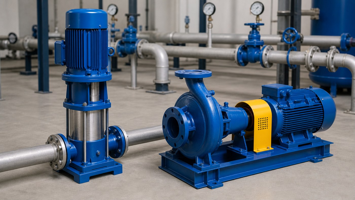
The installation process starts with confirming the duty point: required flow in gallons per minute, total dynamic head in feet, liquid temperature, and system pressure. HVAC systems typically operate with clean water or glycol mixtures, but temperature extremes—especially in hot water or condenser loops—change fluid properties and affect NPSH, seal materials, and bearing lubrication. Before mounting the pump, verify that the nameplate matches the actual service conditions, not just the pipe size.
Foundation and Structural Support Requirements
Vertical inline pumps transfer their weight and operating loads through the pipe flanges and any auxiliary support brackets. Unlike base-mounted pumps with dedicated foundations, inline units rely on the pipe system for both alignment and support. This means the pipe must be independently supported near the pump, with hangers or structural braces that prevent sagging, vibration, and misalignment over time.
Common support mistakes include inadequate pipe restraint upstream and downstream of the pump, flexible couplings too close to the flanges, and reliance on the pump casing to support pipe weight. A properly supported installation uses rigid hangers within two pipe diameters of each flange, with additional support at elbows and valves. If the pipe run includes expansion joints or flexible connectors, place them far enough from the pump that thermal movement does not load the casing or shaft.
For larger pumps or high-pressure services, consider a floor-mounted support stand that carries the pump weight independently. This approach is common in condenser water and primary chilled water loops where pump sizes exceed 10 horsepower and operating pressures reach 150 psi or higher.
Piping Configuration and Flow Path
The suction side of a vertical inline pump should have at least five pipe diameters of straight run upstream of the inlet flange to reduce turbulence and prevent cavitation. Avoid placing elbows, tees, or valves immediately before the suction. If space constraints force a close-coupled elbow, install flow straightening vanes or accept that performance may fall slightly below the published curve.
Discharge piping should include a check valve to prevent backflow when the pump stops, and an isolation valve downstream for maintenance access. Gate or ball valves work better than globe valves in this position because they introduce less head loss. If the system uses variable speed control, confirm that the check valve can handle low-flow conditions without chattering.
For glycol mixtures common in freeze-protected heating or chilled water systems, verify that seals and gaskets are compatible with the fluid. Standard EPDM seals work well with water-glycol blends up to 50%, but higher concentrations or non-standard inhibitors may require Viton or mechanical seal upgrades.
Electrical Connections and Motor Orientation
Verify motor voltage, phase, and frequency against the site electrical supply before wiring. Most HVAC pumps use three-phase motors at 208V, 230V, or 460V. If the pump will run on a variable frequency drive, confirm that the motor is inverter-duty rated and that the drive parameters match the motor nameplate.
Rotation direction matters. Most vertical inline pumps are designed for a specific rotation, typically indicated by an arrow on the volute. Running the pump backward produces no flow or severely reduced performance, and it can damage the impeller and seals. After wiring, bump the starter to confirm rotation before bringing the pump up to full speed.
Overload settings should protect the motor without nuisance tripping during startup or transient load conditions. Set the overload relay at 110-115% of the motor’s full-load amperage unless the manufacturer specifies otherwise. For VFD-controlled pumps, configure the drive’s electronic overload protection to match the motor thermal limits.
Installation Considerations by HVAC Application
| Service Type | Typical Temperature Range | Key Installation Concerns | Seal and Material Notes |
|---|---|---|---|
| Chilled Water | 40-55°F | NPSH margin, condensation on motor housing, insulation clearance | Standard mechanical seals, cast iron or bronze-fitted construction |
| Hot Water Heating | 140-200°F | Thermal expansion, NPSH at elevated temperature, seal face lubrication | High-temperature elastomers (Viton), consider cartridge seals for easier replacement |
| Condenser Water | 70-105°F | Suspended solids, scaling, higher operating pressures, outdoor installation | Abrasion-resistant seals, stainless steel or coated impellers, weather protection |
| Glycol Circulation | Varies | Viscosity effects on head and flow, seal compatibility, freeze protection verification | Confirm elastomer compatibility with glycol type and concentration |
Startup and Commissioning Procedure
Before starting the pump for the first time, confirm that the system is filled, vented, and pressurized. Open the discharge isolation valve fully and crack the suction valve to allow slow filling of the pump casing. Do not run the pump dry—even a few seconds without liquid can damage mechanical seals and score the wear rings.
Once the system is filled and vented, start the pump and immediately check for unusual noise, vibration, or leakage. Record suction pressure, discharge pressure, amperage, and flow if a flowmeter is installed. Compare the measured head (discharge minus suction, converted to feet) against the pump curve at the observed flow. If performance falls significantly below the curve, check for air entrainment, wrong rotation, or a partially closed valve.
Vibration should be minimal. Excessive vibration usually indicates misalignment, cavitation, or resonance with the pipe system. If vibration is present, recheck pipe support, alignment, and NPSH margin before assuming a pump defect.
Common Field Problems and Prevention
Cavitation is the most frequent issue in hot water and high-lift applications. It occurs when suction pressure drops below the liquid’s vapor pressure, forming bubbles that collapse inside the impeller. Symptoms include noise, vibration, and rapid seal or impeller erosion. Prevent cavitation by increasing suction pressure, reducing lift, lowering liquid temperature, or selecting a pump with lower NPSH requirements.
Seal leakage often results from installation errors rather than seal defects. Common causes include misalignment, pipe strain, excessive shaft deflection, and operation at very low flows where cooling is inadequate. Always align the pump and pipe within the manufacturer’s tolerance—typically 0.002 inches per foot of shaft length—and avoid forcing flanges together with bolt torque.
Motor overheating in VFD applications can occur if the drive operates the pump continuously at low speed without adequate cooling airflow. If the system requires extended low-speed operation, verify that the motor has auxiliary cooling or is rated for continuous low-speed duty.
Frequently Asked Questions
Can I replace a horizontal end-suction pump with a vertical inline model in an existing system?
Replacement is possible if the pipe routing allows vertical installation and the floor or structure can accommodate the taller footprint. You will need to modify piping, add support near the flanges, and confirm that the inline model provides the same head and flow at the system’s operating point. Inline pumps typically have different impeller designs and may not match the exact performance curve of the original horizontal unit.
How do I know if my NPSH margin is adequate without detailed system calculations?
Check the pump curve for NPSH required at your operating flow. Then measure suction pressure, convert it to feet of head, and add the static height from the pump centerline to the liquid surface if suction is flooded, or subtract the lift if the pump is above the source. Subtract vapor pressure at the liquid temperature. If the result exceeds NPSH required by at least 3-5 feet, the margin is usually safe. For hot water above 180°F, increase the safety margin to 10 feet or more.
What causes a pump to lose prime after running successfully for weeks or months?
Air leaks on the suction side are the most common cause. Check flange gaskets, shaft seal, and any instrumentation ports below the liquid level. Thermal cycling can loosen bolts over time. Also verify that the system’s expansion tank or air separator is functioning—air accumulation in the high points of the piping can eventually reach the pump suction and break the liquid column.
Should I use a soft starter or VFD with a vertical inline pump in an HVAC system?
A VFD is preferred if the system load varies significantly, such as in variable flow chilled water or hot water loops. The drive allows the pump to match flow to demand, reducing energy consumption and eliminating the need for throttling valves. A soft starter only reduces inrush current during startup and does not provide speed control. If the system operates at constant flow most of the time, a soft starter or across-the-line starter is sufficient and less expensive.
How often should I inspect or service a vertical inline pump in continuous HVAC operation?
Inspect quarterly for leaks, unusual noise, vibration, and bearing temperature. Check motor amperage and compare it to baseline readings. Annual maintenance should include seal inspection or replacement if leakage is observed, bearing lubrication per manufacturer schedule, and alignment verification. If the pump operates in a critical loop like primary chilled water or boiler circulation, consider semi-annual inspections and keep a spare seal kit and bearings on hand.
Conclusion
Vertical inline pump installation in HVAC systems requires attention to duty point verification, structural support, pipe alignment, and startup commissioning. The compact design saves space but places greater demands on pipe support and system preparation. Before approving a pump selection or replacement, confirm that the model matches the actual flow, head, temperature, and control strategy of the hydronic loop. After installation, record baseline performance data—suction pressure, discharge pressure, amperage, and vibration—so future maintenance decisions can be based on measurable changes rather than assumptions. A well-installed vertical inline pump in a properly designed HVAC system will deliver reliable performance for 15-20 years with routine maintenance and periodic seal replacement.