
Selecting a vertical inline pump for commercial buildings requires matching system demand to pump performance while accounting for installation constraints, liquid properties, and operating conditions. The correct pump delivers the required flow at the target head with acceptable efficiency, fits the available space, and operates reliably within the building’s electrical and maintenance infrastructure. This guide walks through the selection process from system analysis to field verification.
Key Takeaways
- Define the duty point (flow and total dynamic head) before reviewing pump models or horsepower ratings.
- Verify suction conditions, pipe configuration, and net positive suction head (NPSH) requirements to prevent cavitation.
- Match motor voltage, enclosure rating, and starter type to the building’s electrical system and ambient conditions.
- Document liquid temperature, viscosity, solids content, and chemical compatibility for seal and material selection.
- Plan for installation access, pipe support, alignment, and future maintenance before finalizing the pump location.
Understanding System Requirements
The selection process begins with system analysis, not catalog browsing. Measure the static lift from the source water level to the highest discharge point. Calculate friction losses through the piping network at the design flow rate, including straight pipe, fittings, valves, and equipment. Add any pressure requirements at the discharge point, such as minimum pressure for chillers, boilers, or terminal units.
Total dynamic head (TDH) equals static head plus friction losses plus discharge pressure requirements. For a chilled water loop with 15 feet of static lift, 35 feet of friction loss, and a 20 psi discharge pressure requirement, the TDH is approximately 15 + 35 + 46 = 96 feet (20 psi converts to roughly 46 feet of head). This is the vertical distance the pump must overcome to move water through the system.
Flow requirements come from load calculations. A 500-ton chiller with a 10°F delta-T requires approximately 1,200 gallons per minute. Confirm the flow rate matches the system design, not an oversized estimate that forces the pump to operate inefficiently.
Pump Curve Analysis
Once you know the duty point, plot it on candidate pump curves. The ideal operating point falls within the center third of the curve, near the best efficiency point (BEP). Operating too far left causes recirculation and low flow issues. Operating too far right increases wear, reduces head, and risks motor overload.
Check the pump curve at the actual operating point, not just at shutoff or maximum flow. A pump rated for 1,500 GPM at 100 feet of head may only deliver 1,200 GPM at 120 feet. If your system requires 1,300 GPM at 115 feet, this pump is undersized despite appearing close on paper.
Verify the impeller diameter and speed shown on the curve match the proposed pump. Some manufacturers show multiple curves for different impeller trims on the same chart. Installing a 10-inch impeller when the calculation assumed 11 inches creates an immediate performance shortfall.
Suction Conditions and NPSH
Vertical inline pumps in commercial buildings typically operate with flooded suction, meaning the water source is above the pump centerline. Confirm the available NPSH exceeds the required NPSH by at least 3 to 5 feet. Available NPSH depends on atmospheric pressure, liquid temperature, static suction head, and friction loss on the suction side.
For hot water systems above 180°F, vapor pressure increases significantly, reducing available NPSH. A condensate pump handling 200°F water requires careful attention to suction design. If the tank is only 2 feet above the pump centerline and suction losses are 1 foot, the available NPSH may be insufficient even though the suction appears flooded.
Avoid suction lift arrangements unless absolutely necessary. If the pump must lift water from below, confirm the total suction lift (static plus friction) stays within the pump’s capability, typically 15 to 25 feet depending on liquid temperature and altitude.
Motor and Electrical Considerations
Match motor voltage to the building’s electrical distribution. Commercial buildings commonly provide 208V, 230V, 460V, or 575V three-phase power. Single-phase motors are limited to smaller pumps, typically under 3 HP. Confirm the motor enclosure rating: open drip-proof (ODP) for indoor mechanical rooms, totally enclosed fan-cooled (TEFC) for damp or dusty locations.
Verify the motor service factor, typically 1.15 for continuous duty applications. This allows the motor to handle brief overloads without damage. Check the full-load amperage against the branch circuit protection and starter size. A 15 HP motor at 460V draws approximately 20 amps; ensure the circuit and starter are rated accordingly.
For variable frequency drive (VFD) operation, confirm the motor is inverter-rated. Standard motors may experience bearing currents or insulation stress under VFD control. Some vertical inline pumps come with shaft grounding to prevent bearing damage from VFD-induced currents.
Material and Seal Selection
Commercial building applications typically use cast iron or bronze-fitted pumps for chilled water, heating water, and domestic water. Stainless steel is preferred for potable water systems to meet plumbing codes and prevent corrosion.
Mechanical seal selection depends on liquid temperature and operating pressure. Standard elastomer seals work well for water below 200°F. Higher temperatures require EPDM, Viton, or PTFE seal faces. Glycol solutions need seals compatible with the specific glycol type and concentration.
For systems with frequent starts and stops, silicon carbide seal faces last longer than carbon against ceramic. Budget the extra cost if the pump cycles more than 10 times per day or operates under variable load conditions.
Installation and Piping
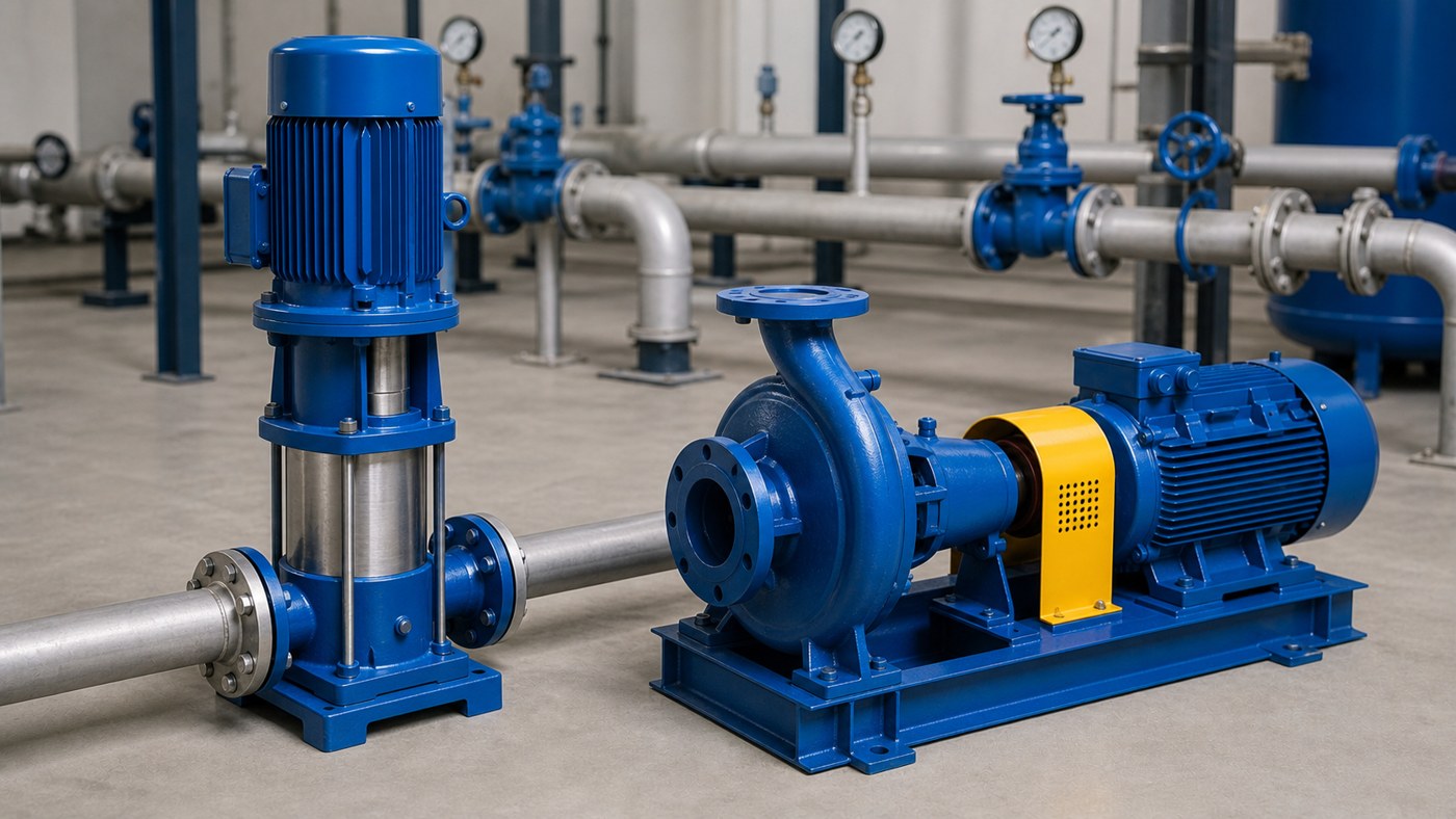
Vertical inline pumps mount directly in the pipeline, reducing the footprint compared to horizontal end-suction pumps. Confirm the pipe size matches the pump connections; reducers add friction loss and disturb flow patterns. Install isolation valves, pressure gauges, and check valves per the manufacturer’s recommendations.
Support the piping independently. Do not use the pump casing to support pipe weight or absorb thermal expansion. Misalignment from pipe strain is a leading cause of seal and bearing failure. Allow at least 5 pipe diameters of straight pipe upstream and 2 diameters downstream for proper flow development.
Verify the pump orientation. Most vertical inline pumps operate with the motor above the impeller, but some models allow motor-down configurations. Check the shaft seal and bearing design to ensure they match the installed orientation.
Selection Comparison Table
| Selection Factor | Typical Range | Verification Method |
|---|---|---|
| Flow rate (GPM) | 50 to 5,000 | Load calculation, manufacturer curve |
| Total dynamic head (ft) | 20 to 300 | System head calculation, field test |
| Liquid temperature (°F) | 40 to 250 | System design, operating logs |
| NPSH available (ft) | 10 to 50 | Calculation from suction conditions |
| Motor horsepower (HP) | 1 to 150 | Pump curve, efficiency, service factor |
| Pipe connection (in) | 2 to 12 | Piping layout, velocity limits |
Field Verification Steps
After installation, test the pump at startup before accepting the system. Measure suction pressure, discharge pressure, amperage, voltage, and flow rate. Compare the results to the design values and pump curve. A discharge pressure of 85 psi when the design called for 95 psi indicates the pump is operating off the curve or the system has higher friction losses than calculated.
Check motor amperage against the nameplate full-load rating. Amperage 10 percent above nameplate suggests the pump is operating beyond the design point, possibly from undersized piping or open bypass valves. Amperage 20 percent below nameplate may indicate a clogged impeller, closed valve, or air binding.
Listen for unusual noise or vibration. Cavitation sounds like gravel passing through the pump. Bearing noise indicates misalignment or inadequate lubrication. Record baseline readings for future comparison.
Common Mistakes to Avoid
- Selecting by horsepower alone without confirming the pump curve matches the system duty point.
- Ignoring NPSH requirements, especially for hot water or high-altitude installations.
- Using suction lift when a flooded suction is possible, increasing the risk of air entrainment and priming problems.
- Oversizing to “be safe,” which forces the pump to operate inefficiently and may cause low-flow recirculation.
- Neglecting pipe support, allowing pipe weight or thermal expansion to strain the pump casing and seals.
- Replacing a failed pump with the same model without investigating the root cause of the failure.
- Assuming VFD compatibility without verifying the motor is inverter-rated and properly grounded.
Frequently Asked Questions
Can I use a single pump curve for systems with multiple operating modes?
No. If the system operates at different flow rates or pressures depending on load or season, plot each operating point on the pump curve. Confirm the pump remains within acceptable operating limits across all modes. A pump optimized for winter heating may cavitate during summer cooling if the flow increases significantly.
What happens if I install a larger impeller than specified?
A larger impeller shifts the pump curve to higher flow and head, potentially overloading the motor. Check the motor horsepower against the power required at the new operating point. If the motor draws more than its rated full-load amperage, it will overheat and fail. Consult the manufacturer before changing impeller sizes.
How do I select a pump when the flow rate varies throughout the day?
Use a variable frequency drive to adjust pump speed based on demand. Select the pump for the maximum flow and head condition, then verify it operates efficiently at part-load conditions when the VFD reduces speed. Avoid operating below 40 percent of design flow for extended periods.
Should I add safety margin to the calculated TDH?
A 5 to 10 percent margin accounts for calculation uncertainty and minor system changes. Do not add 20 or 30 percent; this leads to oversizing, inefficient operation, and excessive energy consumption. If the system is uncertain, measure pressure drop in a similar existing system rather than guessing.
Can I replace a horizontal end-suction pump with a vertical inline pump?
Yes, if the duty point and suction conditions match. Vertical inline pumps save floor space but require adequate pipe support and alignment. Confirm the available NPSH and suction piping configuration meet the vertical inline pump’s requirements. Check the motor mounting orientation and shaft seal design.
What documentation should I provide to a pump supplier for quotation?
Include flow rate, total dynamic head, liquid type and temperature, solids content if applicable, motor voltage and phase, pipe connection size, installation position, operating hours per day, and any relevant codes or standards. For replacement projects, add photos of the existing pump, nameplate, piping, and control panel.
Conclusion
Selecting a vertical inline pump for commercial buildings requires systematic analysis of system requirements, pump performance, installation constraints, and operating conditions. Start with the duty point, verify suction conditions and NPSH, match motor specifications to the electrical system, and plan for field testing. Document the selection rationale so future maintenance teams understand why the pump was chosen and can verify performance against design intent. A well-selected pump operates efficiently, lasts longer, and requires less troubleshooting than one chosen by catalog browsing or rule of thumb.