
Field-style article image prepared for booster pump diagram.
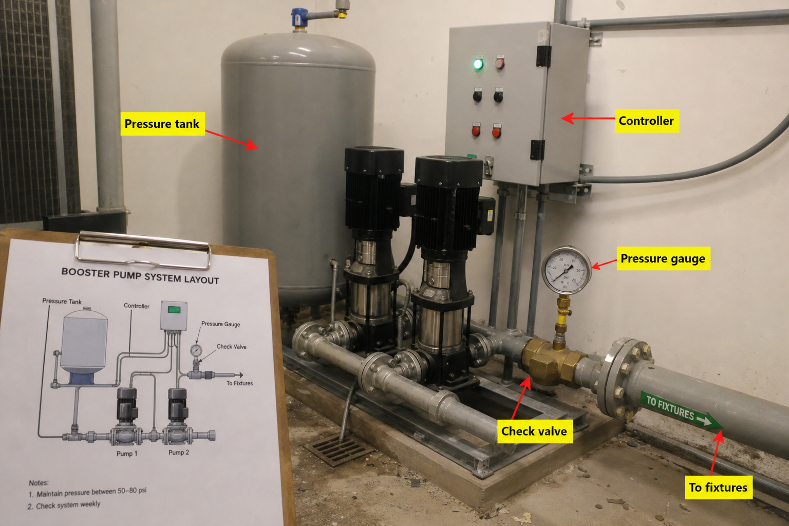
Most booster pump diagram mistakes come from reading pressure at the wrong reference point. The pump inlet, discharge header, pressure tank, and remote fixture can all show different values because elevation and friction losses change the available pressure. A useful diagram marks where each sensor, gauge, check valve, and controller connection belongs.
A booster pump diagram shows the physical arrangement of pumps, storage tank, check valves, pressure sensors, and control components in a pressure-boosting system. The diagram defines suction and discharge piping routes, valve locations, sensor mounting points, and electrical control interfaces required to deliver design pressure at the point of use.
Key Takeaways
- Mark all pressure sensor locations on the diagram with reference elevation; a sensor mounted 10 feet above the pump centerline reads 4.3 psi higher than suction pressure.
- Place check valves on each pump discharge before the common header to prevent backflow when one pump stops; omitting check valves forces all pumps to run continuously.
- Show the atmospheric break or pressure tank upstream of the booster suction; direct connection to municipal supply without a break may violate cross-connection codes.
- Label controller input and output terminals with the actual sensor type (0-10V analog, 4-20mA, dry contact) to match field wiring during installation.
- Include minimum flow bypass or recirculation line on the diagram when system demand drops below 20% of pump rated flow.
Component Layout Sequence
The booster pump diagram follows inlet-to-outlet flow direction. The atmospheric storage tank or break tank appears first, typically elevated 2-3 feet above the pump suction centerline to provide positive suction head.
Suction piping runs from the tank outlet to a common suction header serving all pumps. Size the suction line one pipe size larger than the pump suction flange to keep inlet velocity below 5 feet per second and prevent cavitation.
Each pump connects to the common discharge header through an individual isolation valve and check valve. The isolation valve (gate or ball) allows pump removal without draining the system. The check valve (swing or spring-loaded) closes when the pump stops, preventing reverse flow from the pressurized header.
Pressure Sensor and Controller Placement
The pressure sensor mounts on the discharge header downstream of all check valves, typically 5-10 pipe diameters from the last check valve to avoid turbulence errors. This location measures system delivery pressure, which the controller compares against the setpoint.
Mounting the sensor at a different elevation than the pump discharge changes the reading by 0.433 psi per foot of elevation difference. If the sensor sits 15 feet above the pump, it reads 6.5 psi lower than the actual discharge pressure at the pump flange. Specify sensor location and elevation on the diagram to prevent commissioning confusion.
The pressure controller or variable frequency drive cabinet appears on the diagram as a separate component box with numbered wire runs to each pump motor starter and to the pressure sensor. Label each wire run with gauge, conductor count, and signal type.
Multi-Pump Staging Logic
Systems with two or more pumps require staging control shown on the diagram. The controller starts pump 1 when pressure drops below setpoint, starts pump 2 if pressure continues to drop, and stops pumps in reverse sequence as demand decreases.
Show the lead-lag rotation schedule on the diagram or in an attached control sequence table. Most controllers alternate the lead pump daily or weekly to equalize run hours across all pumps.
Add a common discharge pressure gauge with isolating valve and snubber near the sensor location. This gauge provides manual verification during startup and troubleshooting when the electronic sensor may be miscalibrated or failed.
Check Valve Sizing and Pressure Drop
Check valves introduce 2-8 psi pressure drop depending on valve type and flow velocity. Spring-loaded disc checks create higher drop than swing checks but close faster to prevent column separation and water hammer.
Calculate check valve pressure drop at maximum single-pump flow:
**ΔP = K × (v² / 2g) × (ρ / 144)**
Where:
- ΔP = pressure drop, psi
- K = valve resistance coefficient (2.0-5.0 for swing check, 5.0-10.0 for spring check)
- v = flow velocity, ft/s
- g = gravitational acceleration, 32.2 ft/s²
- ρ = fluid density, lbm/ft³ (62.4 for water)
For a 3-inch swing check valve at 150 gpm:
- Pipe area = 0.0513 ft² (3-inch Schedule 40)
- v = (150 gpm × 0.002228) / 0.0513 = 6.5 ft/s
- K = 3.0 (typical swing check)
- ΔP = 3.0 × (6.5² / 64.4) × (62.4 / 144) = 2.8 psi
Add this pressure drop to the system head requirement when selecting pump size. Undersizing check valves to reduce initial cost increases velocity and pressure drop, forcing the pump to work harder and reducing efficiency.
Tank and Suction Piping Configuration
The atmospheric break tank or bladder pressure tank provides buffer storage and prevents pump cycling on small system leaks. Tank volume typically equals 1-3 minutes of average system flow.
Position the tank outlet at least 12 inches above the bottom to prevent sediment entrainment into the pump suction. Install a float switch or level sensor in the tank with a dry-run interlock to stop all pumps when the water level drops too low.
Show the tank vent on the diagram. Atmospheric tanks require a screened vent sized for maximum fill rate plus maximum pump flow. Undersized vents create partial vacuum that reduces available NPSH and may collapse the tank.
Control Sequence and Safety Interlocks
The booster pump diagram includes control interlocks beyond basic pressure control. Show the following safety stops:
Interlock | Sensor Type | Action | Reset |
Low suction pressure | Pressure switch, 2-5 psi | Stop all pumps | Manual after investigating cause |
High discharge pressure | Pressure switch, 10% above setpoint | Stop running pumps | Automatic when pressure drops |
Motor overload | Thermal relay in starter | Stop affected pump | Automatic after cooling |
Tank low level | Float switch or ultrasonic | Stop all pumps | Automatic when level recovers |
Flow loss | Flow switch, 10% below minimum | Stop pumps after 15-second delay | Manual after checking piping |
Wire all safety interlocks in series on the control circuit so any single fault shuts down the system. Show each interlock sensor location on the piping diagram and wire number on the control diagram.
Bypass and Recirculation Lines
Booster pumps running at low flow rates (below 30% of rated capacity) overheat due to friction losses in the casing. Add a minimum flow bypass line from the discharge header back to the break tank.
Size the bypass for 20-30% of single-pump rated flow. Install a pressure-relief or pressure-regulating valve in the bypass line set 5-10 psi above normal operating pressure. The valve opens only when system demand drops and discharge pressure rises, protecting the pump from deadhead operation.
Show the bypass line with full piping specification: size, material, valve type, and pressure setting. Omitting the bypass line from the diagram often means it gets omitted from installation, leading to pump failure within 6-12 months in low-demand applications.
Electrical Coordination with Control Diagram
The piping diagram shows control component locations, but electrical details appear on a separate control wiring diagram. Cross-reference both diagrams using consistent device tags.
Use standard ISA or IEC tag conventions: PT for pressure transmitter, PS for pressure switch, LT for level transmitter, M for motor. Number each device uniquely (PT-101, PT-102) and show the same tags on both piping and electrical diagrams.
Specify the enclosure rating (NEMA 4X for outdoor or corrosive environments, NEMA 1 for indoor clean spaces) for all control components on the diagram. Field installers need this information to order correct housings and conduit fittings.
FAQs
Where should the pressure sensor be located in a multi-floor building?
Mount the sensor on the floor with the highest required pressure, not at the pump skid in the basement. If the top floor needs 45 psi and sits 60 feet above the pump, you need 71 psi at the pump discharge to deliver 45 psi at elevation (60 ft × 0.433 psi/ft = 26 psi elevation loss). Installing the sensor at the pump would require manual calculation and setpoint adjustment.
Can you connect booster pumps directly to city water without a tank?
Most jurisdictions prohibit direct connection under cross-connection control rules. The booster system may create backpressure into the municipal supply during low-demand periods, potentially contaminating the public system. An atmospheric break tank or approved backflow preventer with intermediate tank is required. Check local plumbing codes before finalizing the diagram.
How do you show duplex versus triplex pump arrangement on the diagram?
Duplex systems show two pumps with 100% capacity each (2 × 100%). Triplex shows three pumps sized for 50-75% capacity each (3 × 50% or 3 × 66%). Label the pump capacity as a percentage of total system design flow on the diagram. This tells the installer whether one pump can carry full load during maintenance or if system capacity is reduced when a pump is offline.
What valve type should be shown between the check valve and discharge header?
Install a gate valve or ball valve between each check valve and the common header to allow check valve servicing without depressurizing the entire system. Some diagrams show the isolation valve upstream of the check valve, which forces you to drain the header to service the check valve. Place isolation valves on both sides of the check valve for maximum maintenance flexibility.
Conclusion
A complete booster pump diagram defines component locations, pipe sizes, valve types, sensor mounting points, and control interlocks required for safe operation. Verify that pressure sensor elevation matches the calculation reference point, that check valves appear on every pump discharge, and that safety interlocks protect against low suction pressure and tank low-level conditions. Cross-check the diagram against local codes for atmospheric break requirements and backflow prevention before submitting for permit approval.