
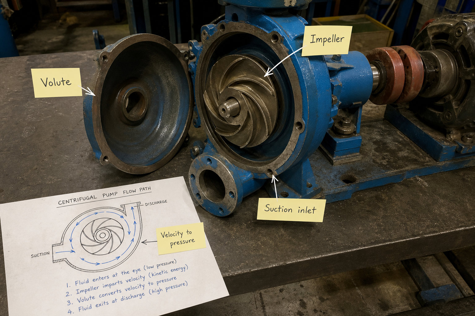
Field-style article image prepared for centrifugal pump working mechanism.
When a centrifugal pump misses its expected duty point, the first question is not only whether the motor is large enough. The real check is how the impeller adds velocity to the liquid, how the volute converts part of that velocity into pressure, and whether the system curve allows the pump to operate near its intended range.
A centrifugal pump converts rotational mechanical energy into fluid velocity and pressure through a spinning impeller that accelerates liquid radially outward. The mechanism depends on three energy-transfer stages: fluid enters the impeller eye axially, gains velocity as impeller vanes accelerate it radially, then converts kinetic energy to static pressure as it decelerates in the volute or diffuser. Performance is constrained by the pump’s head-capacity curve, net positive suction head (NPSH) requirements, and the fluid’s response to centrifugal force at given rotational speeds.
This explanation covers the physical flow path, energy conversion at each stage, how pump curves map mechanism to performance, and the operating limits that determine whether a centrifugal design fits your application.
Key Takeaways
- Centrifugal pumps use impeller rotation to impart velocity, then convert velocity to pressure in the volute—efficiency peaks in a narrow flow range.
- The impeller transfers energy proportional to the square of tip speed; doubling RPM increases head by a factor of four.
- NPSH available must exceed NPSH required to prevent cavitation; suction conditions often limit performance before discharge pressure does.
- Pump curves plot head vs. flow at constant speed; the operating point is where the pump curve intersects the system resistance curve.
- Centrifugal pumps perform poorly at very low flow (overheating, recirculation) and cannot self-prime without initial liquid in the casing.
Impeller Energy Transfer and Velocity Conversion
The impeller is the energy-input component. Liquid enters near the shaft axis through the suction nozzle and impeller eye, where it has low velocity and pressure near atmospheric or the static suction head.
As the impeller rotates, vanes (or blades) catch the fluid and accelerate it radially outward. The centrifugal force pushes liquid from the low-radius eye to the high-radius impeller periphery, increasing its tangential and radial velocity components. The energy added is proportional to the impeller tip speed squared: doubling shaft speed quadruples the theoretical head.
At the impeller discharge, liquid exits at high velocity—often 15 to 30 m/s in industrial pumps—but still at relatively low static pressure. The volute casing (a spiral chamber surrounding the impeller) or a diffuser ring converts this kinetic energy into static pressure by gradually increasing the flow area, which slows the fluid and raises pressure according to Bernoulli’s principle.
The shaft power input (P) relates to flow (Q), head (H), fluid density (ρ), and efficiency (η) as:
P = (ρ × g × Q × H) / η
Where g is gravitational acceleration (9.81 m/s²), Q is in m³/s, H is in meters, and P is in watts. Efficiency accounts for hydraulic losses (friction, turbulence), volumetric losses (internal leakage past wear rings), and mechanical losses (bearings, seals).
Flow Path Geometry and Pressure Development
Liquid flows through four distinct zones, each with a specific energy-conversion role.
**Suction nozzle and impeller eye**: The suction pipe connects to the pump inlet, often with a reducer to match the larger impeller eye diameter. Flow accelerates slightly as it contracts into the eye, reducing static pressure. This is where NPSH available matters—if pressure drops below the fluid’s vapor pressure, cavitation bubbles form.
**Impeller vane channels**: Curved vanes form passages between the inlet and outlet diameters. The number of vanes (typically 4 to 12 for water pumps) and their curvature (backward-curved, radial, or forward-curved) control how efficiently rotational energy converts to fluid velocity. Backward-curved vanes are standard for efficiency and stable performance.
**Volute or diffuser**: The volute is a spiral casing with increasing cross-sectional area. As liquid leaves the impeller at all radial positions, it collects in the volute tongue (cutwater), then spirals outward toward the discharge nozzle. The expanding area reduces velocity and recovers static pressure. Multistage pumps use diffusers—stationary vane rings—instead, guiding flow from one impeller to the next with minimal loss.
**Discharge nozzle**: Collected liquid exits through the discharge flange at the design pressure. Velocity at the discharge is lower than at the impeller tip, but still high enough to require proper piping (gradual enlargement, minimal elbows near the flange) to avoid turbulence losses.
Pump Curves and Operating Point Determination
The pump curve is a graphical map of the mechanism’s performance. It plots total head (H) on the vertical axis against volumetric flow (Q) on the horizontal axis, at a constant impeller diameter and shaft speed.
A typical curve slopes downward from left to right: maximum head occurs at shutoff (zero flow), and head decreases as flow increases due to hydraulic losses in the impeller and volute. The curve also shows efficiency as a series of iso-efficiency contours; peak efficiency usually occurs at 60–80% of maximum flow, called the best efficiency point (BEP).
The operating point is where the pump curve intersects the system curve—a plot of the head required to overcome static lift, pipe friction, and fitting losses at each flow rate. System head increases with flow (friction losses grow with the square of velocity), so the intersection defines the actual delivered flow and pressure.
Performance Prediction Across Speeds
Affinity laws scale performance when speed or impeller diameter changes:
- Flow: Q₂ / Q₁ = (N₂ / N₁) or (D₂ / D₁)
- Head: H₂ / H₁ = (N₂ / N₁)² or (D₂ / D₁)²
- Power: P₂ / P₁ = (N₂ / N₁)³ or (D₂ / D₁)³
Where N is shaft speed (RPM) and D is impeller diameter. These laws assume constant efficiency and similar flow regimes (Reynolds number effects negligible). If the site supervisor’s discharge pressure drops 15%, and the system curve hasn’t changed, the impeller speed or diameter may have decreased—or wear has opened internal clearances, allowing recirculation that doesn’t reach the discharge.
Operating Limits and Mechanism Boundaries
Centrifugal pumps have a usable flow range; operating outside this range causes mechanical damage or poor performance.
**Minimum continuous stable flow**: Below about 30–50% of BEP flow, recirculation occurs at the impeller inlet and outlet. Fluid velocity becomes too low to follow the vane curvature, causing eddies that generate heat, vibration, and accelerated wear. Continuous operation below minimum flow overheats the liquid and can crack the casing due to thermal stress.
**Maximum flow**: Beyond the end of the published curve, head drops steeply and efficiency falls. Shaft power continues to increase (non-overloading characteristic for backward-curved vanes), but NPSH required rises sharply, often causing cavitation. Mechanical limits include bearing load, shaft deflection, and seal life—all worsen as flow increases.
**NPSH requirements**: Net positive suction head required (NPSHᵣ) is the minimum pressure at the impeller eye needed to prevent cavitation. NPSHᵣ increases with flow and speed. NPSH available (NPSHₐ) depends on the suction tank pressure, static suction lift or head, pipe friction loss, and fluid vapor pressure:
NPSHₐ = (Pₛ / ρg) + Hₛ – hₗ – (Pᵥ / ρg)
Where Pₛ is suction tank pressure, Hₛ is static suction head (negative if lift), hₗ is suction line friction loss, and Pᵥ is vapor pressure. NPSHₐ must exceed NPSHᵣ by a safety margin (typically 0.5 to 1 m for water pumps). If NPSHₐ < NPSHᵣ, cavitation bubbles form and collapse near the impeller eye, eroding vanes and creating noise.
Operating Condition | Mechanism Behavior | Consequence |
Below minimum flow | Inlet and outlet recirculation, low vane loading | Overheating, vibration, radial thrust, seal failure |
Near BEP | Smooth flow along vanes, minimal recirculation | Peak efficiency, longest bearing and seal life |
Above maximum flow | High vane loading, rising NPSHᵣ, increased shaft deflection | Cavitation risk, bearing overload, coupling wear |
Insufficient NPSHₐ | Vapor bubbles form at impeller eye, collapse downstream | Pitting, noise, head loss, flow instability |
Dead-head (shutoff) | No flow, impeller churns fluid, all energy becomes heat | Rapid temperature rise, casing thermal stress, seal damage |
Application Matching and Installation Considerations
The mechanism determines what applications suit centrifugal pumps and which require other designs.
Centrifugal pumps excel at high-flow, moderate-head applications with clean to slightly contaminated liquids. They cannot self-prime—the casing must be filled with liquid before startup because the impeller cannot generate enough suction to lift liquid from a dry sump. Priming methods include foot valves, vacuum pumps, or locating the pump below the liquid level (flooded suction).
Viscosity affects performance. The mechanism relies on fluid inertia and Bernoulli conversion, which work best with low-viscosity liquids (water, light hydrocarbons). At viscosities above 100 cP, head, flow, and efficiency drop; correction factors from Hydraulic Institute standards predict the derating. Positive displacement pumps become more efficient above 500 cP.
Solids handling depends on impeller type. Closed impellers (with front and back shrouds) deliver the highest efficiency but clog easily. Open or semi-open impellers tolerate fibrous solids, but wear faster and lose performance as tip clearances increase. Recessed impellers or vortex designs pass large solids (up to 3 inches) but sacrifice head and efficiency.
Suction piping layout directly affects NPSHₐ. Long horizontal runs, elbows near the inlet, and reducers that aren’t concentric (eccentric reducers prevent air pockets) all increase suction losses. A straight run of 5–10 pipe diameters upstream of the pump inlet improves flow distribution into the impeller eye.
FAQs
Can a centrifugal pump run backward if the motor reverses?
Yes, and it will generate head and flow in the reverse direction, but at much lower efficiency and potentially damaging vibration. Backward rotation changes the vane angle relative to the flow direction, creating turbulence and off-design loading. Check rotation before commissioning and after any motor or coupling work.
Why does discharge pressure fluctuate when the pump runs at constant speed?
Fluctuating pressure often indicates operation near the curve’s unstable region (low flow, steep slope) or air entrainment in the suction. If the system curve intersects the pump curve where dH/dQ is steep, small changes in system resistance cause large pressure swings. Air pockets compress and expand, creating pulses. Vent the casing and check for suction-side leaks.
How does impeller wear affect the working mechanism?
Wear increases the clearance between impeller shrouds and the casing wear rings, allowing liquid to recirculate from the high-pressure discharge zone back to the low-pressure eye. This internal leakage reduces delivered flow at a given head and shifts the curve downward. Efficiency drops because the impeller re-handles the same liquid multiple times. Replace wear rings or the impeller when measured clearances exceed manufacturer tolerances.
Do centrifugal pumps work with gases or two-phase mixtures?
Standard centrifugal pumps fail with pure gases—density is too low for the impeller to generate measurable head. For two-phase (gas-liquid) mixtures below about 6% gas by volume, performance degrades but the pump still operates. Above 10% gas, the mechanism breaks down: gas pockets block vane channels, head collapses, and flow becomes erratic. Specialized designs (semi-open impellers, inducers) extend the gas tolerance slightly, but positive displacement or dedicated gas compressors handle high gas fractions.
Conclusion
The centrifugal pump working mechanism converts shaft rotation into fluid pressure through three stages: axial entry, radial acceleration by the impeller, and velocity-to-pressure conversion in the volute. Performance maps to the pump curve, where the operating point must sit near the best efficiency point to avoid recirculation, overheating, or cavitation.
Before specifying a centrifugal pump, confirm that NPSH available exceeds required by at least 0.5 m, the expected flow falls within 70–120% of BEP, and the fluid viscosity stays below 100 cP. For the scenario in the opening—discharge pressure dropping under load—verify the actual shaft speed with a tachometer, check wear ring clearances, and compare the measured operating point to the original curve at the confirmed speed. If the mechanism is intact but the curve has shifted, internal wear is consuming energy that should reach the discharge.