
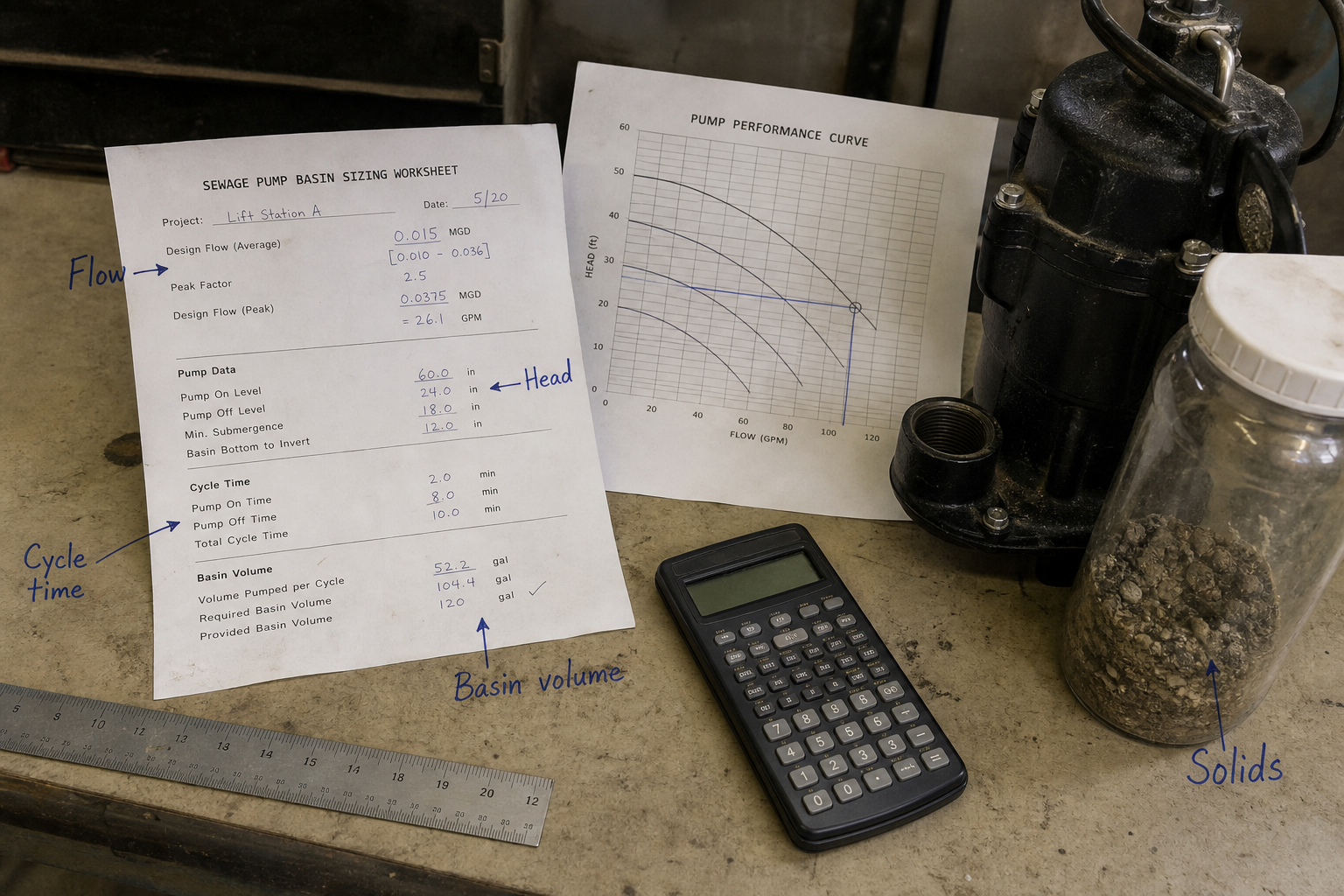
Field-style article image prepared for sewage pump sizing calculator.
A sewage pump sizing calculator determines the minimum flow rate, total dynamic head, solids-handling clearance, and basin cycling frequency needed to lift wastewater containing suspended solids from a collection basin to a discharge point or gravity sewer. Correct sizing prevents clogging, basin overflow, motor overload, and premature seal failure. The calculation integrates peak inflow rate, static lift, friction loss, minimum run time, and the largest solid diameter the impeller must pass without damage.
Key Takeaways
- Flow rate must exceed peak inflow by 20–50% to prevent basin overflow during demand surges and account for impeller wear over service life.
- Total dynamic head combines static lift, friction loss in the discharge pipe, and pressure at the discharge point; undersizing causes low flow and basin backup.
- Solids clearance requires impeller vane spacing and volute throat diameter at least 3 inches (75 mm) for municipal sewage; industrial wastewater may require 4–6 inches depending on process solids.
- Basin cycling limits depend on motor cooling; submersible sewage pumps typically need 6–10 minute minimum run times to prevent thermal overload from frequent starts.
Flow Rate Calculation for Peak Inflow
Start with the peak inflow rate to the basin, measured in gallons per minute (GPM) or cubic meters per hour (m³/h). For municipal lift stations, use the design population equivalent times the per-capita flow rate during wet-weather events. For industrial wastewater, calculate from the largest simultaneous discharge from all connected processes.
The pump flow rate Q_pump must satisfy:
Q_pump ≥ Q_peak × SF
Where:
- Q_pump = pump rated flow at operating head (GPM)
- Q_peak = peak inflow rate to basin (GPM)
- SF = safety factor, typically 1.2–1.5
The safety factor accounts for impeller wear, future flow increases, and the time required for the pump to draw down the basin between cycles. A duplex system with two pumps uses SF = 1.2 because the second pump provides backup capacity. A simplex system requires SF ≥ 1.4 to handle inflow during pump maintenance or failure recovery.
Total Dynamic Head Components
Total dynamic head (TDH) determines the pressure the pump must generate to move sewage from the basin liquid level to the discharge point. Calculate TDH as:
TDH = H_static + H_friction + H_discharge
Where:
- H_static = vertical distance from minimum basin level to discharge point (feet or meters)
- H_friction = friction loss in discharge piping, fittings, and valves (feet or meters)
- H_discharge = pressure head at discharge point if above atmospheric (feet or meters)
Static head is fixed by site elevation. Friction head varies with flow rate and pipe characteristics. Use the Hazen-Williams equation for friction loss in clean pipes:
H_friction = (4.52 × Q^1.85 × L) / (C^1.85 × D^4.87)
For sewage applications in the United States:
- Q = flow rate (GPM)
- L = pipe length (feet)
- C = Hazen-Williams coefficient (typically 100 for PVC, 130 for new ductile iron with lining)
- D = inside pipe diameter (inches)
- H_friction = friction head loss (feet)
Add 10–15% to calculated friction loss to account for biofilm buildup and reduced effective diameter over 2–5 years of service.
Solids Clearance and Impeller Selection
Sewage pumps must pass the largest solid expected in the waste stream without clogging or damage. Municipal sewage standards typically specify 3-inch (75 mm) spherical solids clearance for residential systems. Industrial facilities processing fibrous materials, plastic waste, or large organic matter may require 4–6 inch clearance.
Three impeller configurations handle different solid types:
**Vortex impellers** create a vortex that suspends solids without direct impeller contact. They pass large solids and stringy materials but deliver 10–20% less head than enclosed impellers at the same diameter and speed. Use for applications with rags, plastic bags, or fibrous organic waste.
**Open or semi-open impellers** have 2–3 vanes with large inter-vane passages. They handle 3-inch spherical solids and moderate fibrous content. Efficiency drops 5–15% as wear increases vane-to-volute clearance. Inspect and adjust clearance every 6–12 months in abrasive service.
**Enclosed impellers with recessed vanes** provide the highest efficiency but require clean inlet screens or grinders to protect against stringy materials. Use only when upstream screening removes solids larger than 1 inch and fibrous content is minimal.
Basin Cycling and Pump Runtime Control
Basin cycling frequency affects motor life, mixing, and septicity prevention. The pump must run long enough for the motor to dissipate start-up heat before the next cycle begins.
Minimum run time T_min depends on motor thermal class and cooling method:
T_min = (Motor starts per hour limit)^-1 × 60 minutes
Submersible sewage pumps with wet-rotor cooling typically allow 6–20 starts per hour, giving T_min = 3–10 minutes. Dry-pit pumps with forced-air cooling may allow 20–30 starts per hour, reducing T_min to 2–3 minutes.
Calculate actual run time from basin volume and pump flow rate:
T_run = (V_basin × ΔL) / Q_pump
Where:
- V_basin = basin surface area (square feet or square meters)
- ΔL = level change between pump start and stop (feet or meters)
- Q_pump = pump flow rate (GPM or m³/h, converted to consistent units)
- T_run = pump runtime (minutes)
If T_run < T_min, increase the level difference ΔL between start and stop or reduce pump capacity. If T_run > 30 minutes during low-flow periods, septicity may develop in the basin. Add recirculation or reduce ΔL to increase cycling frequency.
Selecting Pump Curve Operating Point
Plot the system curve and pump curve on the same head-flow chart. The system curve shows TDH versus flow rate; it rises as flow increases due to higher friction losses. The pump curve shows the head the pump delivers at each flow rate; it typically falls as flow increases.
The operating point is where the curves intersect. For sewage applications, select a pump whose best efficiency point (BEP) falls within 80–110% of the required operating flow rate. Operating too far left of BEP causes flow recirculation and vibration. Operating too far right reduces head margin and risks motor overload.
Verify the operating point delivers the calculated TDH at the required flow rate. If the pump curve falls below the system curve at the design flow, the pump cannot meet the duty. Select a larger impeller diameter, higher speed, or different pump model.
Check the motor power requirement at the operating point:
P_motor = (Q × TDH × SG) / (3,960 × η_pump)
Where:
- P_motor = motor power requirement (horsepower)
- Q = flow rate (GPM)
- TDH = total dynamic head (feet)
- SG = specific gravity (1.0–1.05 for typical sewage)
- η_pump = pump efficiency at operating point (decimal, from pump curve)
Add 15–25% service factor to the calculated motor power to prevent overload during transient conditions or when solids accumulate on the impeller.
FAQs
What happens if the sewage pump is undersized for flow rate?
The basin fills faster than the pump can evacuate it, leading to overflow through relief pipes or manhole covers. High-level alarms trigger frequently, and the pump runs continuously during peak flow periods without drawing the basin down. Upgrade to a higher-capacity pump or add a second pump in a duplex configuration.
How do I account for future flow increases in initial sizing?
Multiply current peak flow by a growth factor based on planned development or process expansion over the pump’s 15–20 year service life. For municipal systems, use population projections from local planning authorities. For industrial sites, coordinate with process engineering to estimate production increases. A 20–40% future capacity allowance is typical for greenfield installations.
Can I use a clean-water pump with higher efficiency instead of a sewage pump?
Clean-water pumps lack the solids clearance, seal protection, and impeller geometry needed for sewage service. They clog within hours or days and suffer seal failure from abrasive particles and fibrous materials. Use only pumps rated for sewage or wastewater service with appropriate solids-handling capability.
What minimum pipe velocity prevents solids settling in the discharge line?
Maintain 2–3 feet per second (0.6–0.9 m/s) minimum velocity in horizontal runs to prevent solids deposition. Calculate velocity as V = Q / (2.448 × D²) where Q is in GPM and D is pipe inside diameter in inches. If velocity falls below 2 fps at design flow, reduce pipe diameter or increase flow rate.
Conclusion
Sewage pump sizing integrates flow rate margin, total dynamic head calculation, solids clearance matching, and basin cycling verification into a single selection process. Start with peak inflow and safety factor to establish flow requirements, then calculate static and friction head components to define the operating point. Match impeller type and clearance to expected solids, and verify that basin geometry and pump capacity deliver acceptable run times without thermal overload. Before finalizing the selection, confirm the pump curve intersects the system curve within 20% of BEP and that motor power includes adequate service factor for transient conditions.