
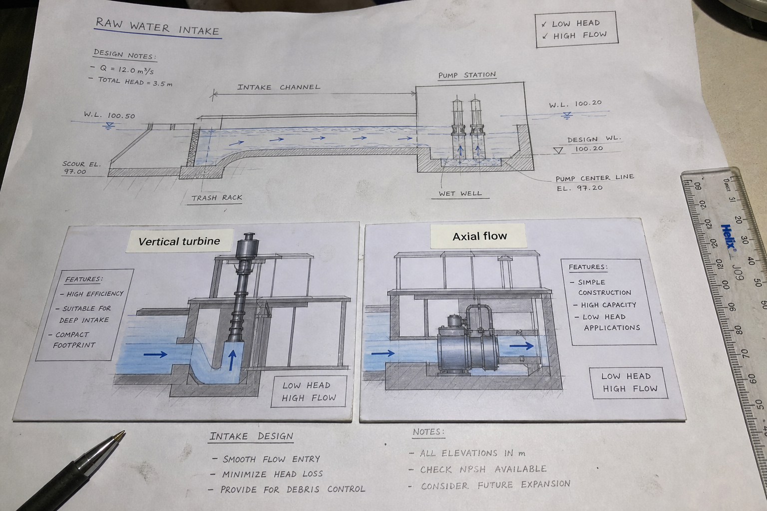
Field-style article image prepared for vertical turbine vs axial flow pumps raw water intake.
Raw water intake pump selection usually starts with the head-flow relationship. Vertical turbine pumps develop higher head through one or more centrifugal bowl stages in a vertical column, while axial flow pumps move large volumes at low head by accelerating water parallel to the shaft. The right choice depends on total dynamic head, required flow rate, submergence, debris control, and intake structure geometry.
Key Takeaways
Vertical turbine pumps suit raw water intake applications requiring 50 to 400 feet of total head, with flows from 500 to 10,000 GPM per pump. Each bowl stage adds 15 to 40 feet of head depending on impeller diameter and speed.
Axial flow pumps handle 2,000 to 50,000 GPM at heads below 50 feet. The single-stage propeller design requires less submergence depth but demands a bell-mouth or elbow intake to minimize inlet losses.
Intake structure cost scales with excavation depth and pump column length. Vertical turbine installations allow smaller diameter wet wells but require deeper excavation to maintain submergence over the top bowl. Axial flow pumps tolerate shallower sumps but need wider intake bays to support larger impeller diameters.
Head-Flow Operating Range
Vertical turbine pumps generate head through centrifugal force in radial-flow or mixed-flow bowls stacked along a vertical lineshaft. Each bowl contributes head additively: a four-bowl pump with 30 feet per stage delivers 120 feet at design flow. Efficiency peaks at 75 to 84 percent in the 0.6 to 1.0 Qdesign range.
The impeller diameter and rotational speed determine specific speed, Ns = N√Q / H^0.75, where N is RPM, Q is flow in GPM, and H is head per stage in feet. Raw water turbine pumps typically operate at Ns between 1,500 and 4,000, balancing head per stage against efficiency.
Axial flow pumps accelerate fluid along the shaft axis through a propeller impeller. Head is limited by the single-stage design and blade tip speed. A 1,200 RPM, 36-inch diameter axial flow pump delivers 8,000 GPM at 30 feet of head with efficiency near 86 percent.
Specific speed for axial flow designs exceeds 8,000, indicating very high flow relative to head. The steep pump curve means small head changes cause large flow variations, requiring careful system-curve matching.
Intake Geometry and Submergence
Vertical turbine pumps mount in wet wells or intake structures with the suction bell submerged below minimum water level. Minimum submergence S = D(0.5 + 2.3V²/2g), where D is bell diameter in feet, V is bell velocity in ft/s, and g is gravitational acceleration. For a 12-inch bell at 8 ft/s, S = 1.0(0.5 + 2.3 × 64 / 64.4) = 2.8 feet below the bell.
The column pipe extends from the discharge head to the top bowl, with lineshaft or submersible motor drive. Pump length drives wet well depth: a 120-foot head pump with four 30-foot stages requires roughly 15 feet of column length plus bowl assembly depth.
Axial flow pumps install in vertical or horizontal orientations. Vertical sump installations use a bellmouth or elbow intake immediately upstream of the impeller. Horizontal installations require an approach channel with flow straightening to prevent pre-rotation and efficiency loss.
Intake velocity should remain below 5 ft/s at the bellmouth entrance to avoid vortex formation. For an 8,000 GPM axial flow pump with a 36-inch diameter intake, approach velocity is 8,000 × 0.002228 / (π × 1.5²) = 2.5 ft/s, which is acceptable.
Submergence for axial flow pumps depends on impeller depth and Froude number. Minimum submergence S = D(1.0 + 2.0Fr), where D is impeller diameter and Fr = V / √(gD). Surface-piercing vortices form when submergence falls below this limit.
Selection Criteria for Raw Water Intake
Parameter | Vertical Turbine | Axial Flow |
Head range | 50–400 ft | 10–50 ft |
Flow per pump | 500–10,000 GPM | 2,000–50,000 GPM |
Efficiency peak | 75–84% | 82–88% |
Specific speed | 1,500–4,000 | 8,000–15,000 |
Submergence | 3–8 ft over top bowl | 1.5–3 × impeller diameter |
Intake width | 2–4 × bell diameter | 4–6 × impeller diameter |
Column length impact | High (adds to well depth) | Low (short shaft) |
Total dynamic head governs the primary selection. Calculate TDH = static lift + friction loss + velocity head + system pressure. For raw water intake from a reservoir to a treatment plant clearwell at 80 feet elevation with 15 feet of friction loss, TDH = 80 + 15 + velocity head. A 2,000 GPM flow through 12-inch pipe yields velocity head of 1.0 foot, giving TDH = 96 feet.
This application requires a vertical turbine pump. An axial flow pump cannot develop 96 feet of head without multiple stages, which negates its design advantage.
Low-head, high-flow applications favor axial flow designs. A flood-control pumping station evacuating stormwater at 25,000 GPM against 18 feet of head uses axial flow pumps. The alternative—five 5,000 GPM vertical turbine pumps—increases motor count and control complexity.
Operating Considerations
Vertical turbine pumps tolerate solids and debris common in raw water if bowl velocities stay below erosion limits. Bronze or stainless-steel bowl assemblies resist corrosion in fresh water. Enclosed lineshaft designs protect the drive shaft from grit infiltration.
Minimum flow to prevent overheating is 20 to 30 percent of design flow for oil-lubricated bearings. Water-lubricated rubber bearings tolerate lower flows but wear faster in silty water.
Axial flow pumps require clean intake screens to prevent blade fouling. Debris wrapping around the propeller hub unbalances the rotor and causes vibration. Trash racks with 3-inch bar spacing upstream of the pump protect the impeller.
The steep head-flow curve means operating far from design flow causes efficiency loss and potential cavitation. Control strategies include variable-frequency drives to match flow demand or throttling discharge valves, though throttling wastes energy.
Installation and First Cost
Vertical turbine pumps require deeper excavation but smaller plan area. A four-pump station with 3,000 GPM per pump fits in a 20-foot by 30-foot wet well if pumps are spaced at 4-foot centers. Wet well depth must accommodate static water level, drawdown during operation, pump column length, and minimum submergence.
Axial flow installations use shallower sumps but wider intake bays. The same 12,000 GPM capacity with three 4,000 GPM axial flow pumps needs a 40-foot by 30-foot sump to maintain proper approach flow. Excavation volume may be similar despite reduced depth.
Motor mounting differs. Vertical turbine pumps use hollow-shaft motors or right-angle gear drives on a discharge head at grade. Axial flow pumps in vertical sumps mount the motor above the sump with a short shaft, or use submersible motors integral with the pump.
Foundation loads concentrate at the discharge head for turbine pumps, with lateral support at the pump base. Axial flow pumps distribute thrust across the motor mount and pump flange, requiring stiffer structural support.
FAQs
Can vertical turbine pumps handle variable water levels in reservoirs?
Vertical turbine pumps accommodate water level variation as long as minimum submergence over the top bowl is maintained. Multi-stage pumps with the top bowl at 10 feet below minimum water level operate through 20 to 30 feet of level swing without depriming. Longer columns increase first cost but eliminate the need for wet well level control.
Do axial flow pumps require special startup procedures?
Axial flow pumps must start with the discharge valve fully open to avoid overloading the motor. The low shutoff head means torque is highest at design flow, opposite to centrifugal pump behavior. Closing the discharge valve after startup reduces flow and motor load, but operating far from design flow risks cavitation and low efficiency.
How does intake vortex risk differ between pump types?
Vertical turbine pumps with deep-set suction bells are less prone to surface vortices but can form submerged vortices if approach velocity exceeds 1.5 ft/s or if inlet flow is asymmetric. Axial flow pumps with shallow submergence form surface vortices more readily, especially in wide sumps with low approach velocity and inadequate flow distribution. Anti-vortex baffles or curtain walls correct this.
What motor speed is typical for raw water intake pumps?
Vertical turbine pumps use 1,200 or 1,800 RPM motors for municipal water service. Higher speeds reduce bowl diameter and first cost but increase wear in abrasive water. Axial flow pumps run at 900 to 1,200 RPM to limit blade tip speed and cavitation risk. Variable-frequency drives allow speed adjustment for seasonal flow variation.
Conclusion
Select vertical turbine pumps when total dynamic head exceeds 50 feet or when intake structure depth is not constrained. Use axial flow pumps for heads below 30 feet with flows above 5,000 GPM per pump, accepting the trade-off of wider intake bays and steeper pump curves. Confirm minimum submergence, approach velocity, and anti-vortex measures during intake structure design. Verify motor sizing at both minimum and maximum water levels before specifying column length and bowl stages.