
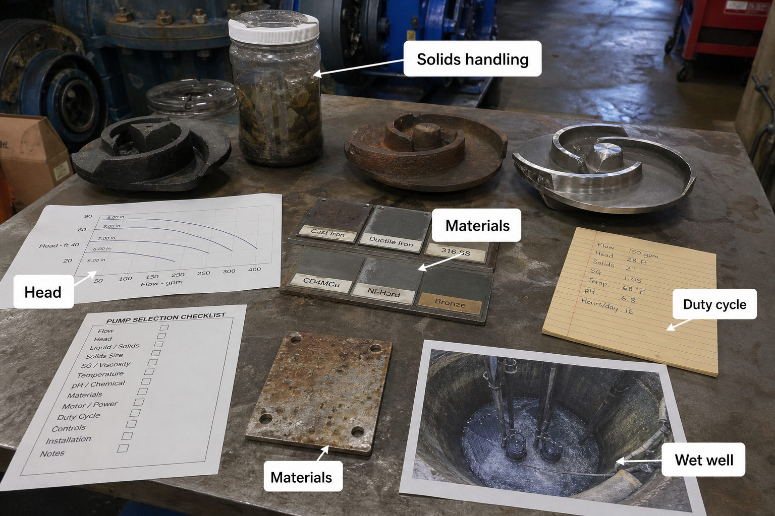
Field-style article image prepared for wastewater pump selection.
Wastewater pump selection cannot rely on solids size alone. Rags, wipes, grease, grit, corrosive liquid, intermittent inflow, and wet-well geometry all change how a pump behaves after installation. A reliable selection matches solids-handling geometry, total dynamic head across the operating range, wetted material compatibility, and station duty cycle before model selection begins.
The selection process is valid when you have confirmed flow range, static and friction head, fluid characteristics including pH and temperature, piping layout with all fittings counted, control scheme, and duty cycle. It remains incomplete without local codes, manufacturer pump curves for the specific impeller trim, and site-specific constraints such as available NPSH or submerged depth.
Key Takeaways
- Match impeller passage size and geometry to the largest expected solid dimension and shape, not just spherical particle diameter.
- Calculate total dynamic head as static lift plus friction loss across minimum, rated, and maximum flow to verify the pump operates in the efficient curve region at all conditions.
- Select elastomer and metal grades based on fluid pH, temperature, abrasive load, and exposure time, not just generic "wastewater" ratings.
- Confirm duty cycle including starts per hour, run time per cycle, and alternation logic stays within motor thermal limits and seal design life.
Solids Handling Geometry and Impeller Type
Wastewater solids fall into three handling categories: spherical particles up to a specified diameter, fibrous or stringy material that forms rope-like masses, and abrasive grit that erodes impeller surfaces. A 3-inch solids passage refers to the minimum clear dimension through the impeller vanes and volute throat, allowing a 3-inch sphere to pass without jamming.
Recessed impellers or vortex designs create a flow pattern that keeps solids away from the impeller entirely, trading efficiency for near-zero clog risk. These suit raw sewage with heavy rag content but deliver 5 to 15 percent lower head at the same speed compared to enclosed non-clog impellers. Enclosed non-clog impellers with two or three thick vanes handle fibrous material better than radial-vane designs but still require a minimum flow velocity—typically 3 feet per second in the suction pipe—to prevent settlement.
When rags or wipes dominate the waste stream, specify a cutter or macerator system upstream or select a pump with an integral grinder. The macerator reduces solids to sub-half-inch fragments, allowing use of standard enclosed impellers with higher efficiency but adding maintenance on the cutter blades.
Total Dynamic Head Calculation and Curve Matching
Total dynamic head (TDH) is the sum of static head, friction head, and pressure head at the discharge point. Static head is the vertical distance from the pump centerline to the discharge elevation. Friction head depends on pipe diameter, length, material roughness, and the number of fittings.
Use the Darcy-Weisbach equation or Hazen-Williams equation with the appropriate C-factor for wastewater piping—typically C = 100 for coated steel or 130 for PVC. Count every elbow, valve, and fitting as equivalent length. A 90-degree elbow in 6-inch pipe adds roughly 15 feet of equivalent length; a gate valve adds 5 feet.
Calculate TDH at three flow points: minimum flow when one pump runs in a duplex station, rated flow at the design point, and maximum flow if both pumps run simultaneously. Plot these three points on the pump manufacturer’s curve. The operating range should fall in the middle third of the curve, avoiding the steep run-out region on the right and the unstable low-flow region on the left.
A pump selected for 250 GPM at 35 feet TDH must also handle 125 GPM at roughly 42 feet TDH without operating at shutoff head and 400 GPM at 28 feet TDH without running off the end of the curve into cavitation. If the system curve crosses the pump curve too far right, the pump will overload the motor and risk seal failure from high stuffing box pressure.
Material Selection for Wetted Components
Cast iron is the baseline housing material for municipal wastewater pumps, providing adequate corrosion resistance in pH 6 to 9 environments with temperatures below 104°F. When pH drops below 6 or rises above 10, or when hydrogen sulfide concentration creates aggressive corrosion, upgrade to 316 stainless steel for the impeller and volute or specify a corrosion-resistant coating such as epoxy or ceramic-reinforced polymer.
Elastomers in the mechanical seal face the same fluid but operate at higher surface speeds and temperatures. Buna-N (nitrile) handles standard sewage but degrades in oils and solvents. Ethylene propylene (EPDM) resists water-based fluids and mild acids but swells in petroleum products. Fluoroelastomer (Viton) provides broad chemical resistance but costs three to four times Buna-N and requires higher seating force.
Abrasive grit—silica sand, concrete fragments, or metal particles—erodes impeller leading edges and volute walls. Standard cast iron wears at roughly 0.020 inch per 1,000 hours in moderate grit service. Upgrade to hardened alloy such as Ni-Hard or apply tungsten carbide coatings to impeller vanes when grit loading exceeds 500 ppm or particle hardness exceeds 6 Mohs.
Check manufacturer documentation for specific material limits. A pump rated for "wastewater service" in cast iron typically assumes pH 6.5 to 8.5, temperature under 104°F, and less than 200 ppm abrasive solids. Operation outside those bounds voids the corrosion warranty and shortens seal life.
Station Duty Cycle and Pump Sequencing
A lift station with a 1,000-gallon wet well receiving 100 GPM average inflow will cycle pumps on and off every 10 minutes if a single 250 GPM pump handles the flow. Motor starts per hour should not exceed the manufacturer’s thermal limit—typically six starts per hour for NEMA design B motors in continuous-duty service.
Lead-lag alternation extends bearing and seal life by distributing wear across both pumps. Program the controller to alternate which pump starts first on each cycle, so Pump 1 runs for half the daily cycles and Pump 2 for the other half. Level switches or pressure transducers trigger starts at high level and stops at low level, with a lag pump start level in between.
When inflow exceeds the capacity of one pump, the lag pump starts before the lead pump reaches shutoff or cavitation. This requires a third level switch or a timed delay after the lead pump starts. If both pumps run continuously during peak inflow, verify that the combined flow does not push either pump past the right edge of its curve into overload.
Submersible pumps installed in the wet well must remain submerged to avoid overheating. Dry-pit pumps in a separate chamber require a low-level cutoff to prevent seal damage and motor burnout if the suction line loses prime. Set the low-level cutoff at least 12 inches above the suction pipe inlet for vertical turbine pumps or 6 inches above the impeller centerline for horizontal end-suction pumps.
FAQs
What NPSH margin should I specify for wastewater pumps?
Net positive suction head available (NPSHA) must exceed the pump’s NPSH required (NPSHR) by at least 3 feet across the entire operating range. Wastewater contains dissolved gases and air entrained from turbulent flow at the wet well inlet, so use a 5-foot margin when suction conditions are marginal. Calculate NPSHA as atmospheric pressure head plus static submergence minus vapor pressure head minus suction line friction losses.
Should wastewater lift stations use variable-frequency drives?
VFDs smooth starts and reduce power consumption when inflow varies widely, but they add cost and complexity. A station with steady baseload flow and simple on-off control does not benefit from VFD speed modulation. When inflow swings from 50 GPM overnight to 400 GPM during morning peak, a VFD allows one pump to ramp speed and match inflow rather than cycling on and off every few minutes. VFDs also extend seal life by reducing start-stop cycles.
When should a station use three pumps instead of two?
Triplex stations with three pumps—two duty and one standby—provide redundancy when the consequence of pump failure is high or when maintenance access is limited. Municipal codes in some jurisdictions require N+1 redundancy for stations serving more than 50 homes or critical facilities. The third pump also allows one pump to remain offline for service while the other two handle peak flow, avoiding emergency repairs during weekends or after hours.
How do grinder pumps differ from solids-handling wastewater pumps?
Grinder pumps macerate solids to slurry before pumping, allowing use of smaller-diameter piping and standard centrifugal impellers. They suit residential pressure sewer systems where small-bore force mains—typically 2 to 4 inches—connect individual homes to a central collection point. Solids-handling pumps in lift stations move raw sewage without grinding, requiring larger impeller passages and piping but avoiding the maintenance burden of cutter mechanisms.
Conclusion
Select wastewater pumps by confirming solids passage matches the worst-case material dimension and shape, not just the average particle size. Calculate TDH at minimum, rated, and peak flow to ensure the operating points fall in the efficient center region of the pump curve. Specify wetted materials and elastomers based on actual pH, temperature, and abrasive load from fluid testing, not generic "wastewater" ratings. Verify that motor starts per hour, run time per cycle, and wet-well level control logic stay within thermal and mechanical limits before releasing the specification for bid.