
title: "Centrifugal Pump Parts: Names, Functions, and Diagram"
description: "Identify the main components, understand what each one does, and connect the diagram to inspection and pump selection in real industrial systems."
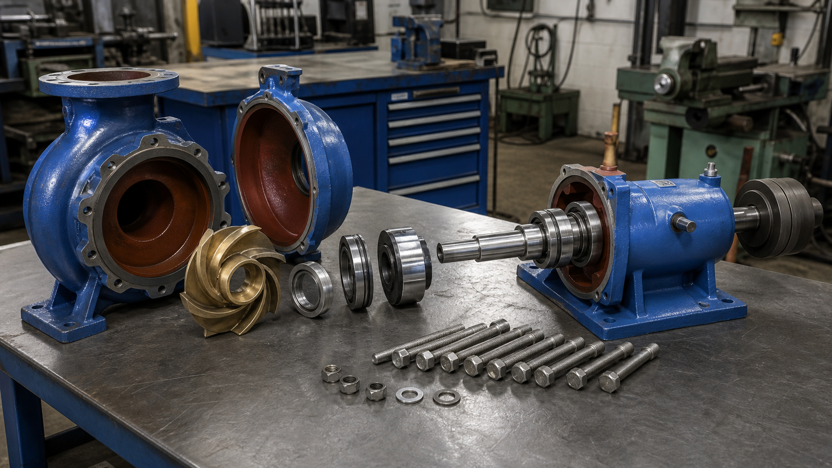
A centrifugal pump converts shaft rotation into fluid pressure by accelerating liquid through an impeller and converting velocity to static head in a surrounding casing. Each component controls a specific loss mechanism or load path. Understanding where energy escapes and where mechanical loads concentrate guides inspection planning, failure diagnosis, and replacement decisions.
This article traces the hydraulic path from suction flange through discharge nozzle, then follows the mechanical load path from driver to bearing housing. The goal is to connect each part name to a measurable wear limit, performance shift, or maintenance trigger documented in the manufacturer’s data package.
Key Takeaways
- The flow path enters at the suction flange, accelerates through the impeller eye and vanes, then decelerates in the volute or diffuser before exiting the discharge flange; head loss accumulates at every geometry change.
- Wear rings control internal recirculation between discharge and suction zones; clearance growth reduces efficiency and shifts the pump curve leftward on the flow axis.
- The mechanical seal or packing assembly seals the shaft penetration; seal chamber pressure, flush flow rate, and face temperature govern seal life and leakage rate.
- Bearings position the shaft under combined radial and axial loads; vibration trending detects developing problems weeks before bearing failure forces an unplanned shutdown.
- Inspection and replacement limits come from the manufacturer’s tolerance tables and measured conditions, not from universal rules applied across all pump models.
Read the Pump from Suction Flange to Driver
Liquid enters through the suction flange. The flange diameter and pressure class must match the system piping; a reducer placed immediately upstream creates velocity gradients that reach the impeller eye and increase NPSHr. Eccentric reducers with the flat side on top reduce air pocket formation but must match the pump manufacturer’s inlet drawing.
The suction nozzle cast into the casing guides flow toward the impeller eye with minimal direction change. When the system’s available NPSH (NPSHa) falls below the pump’s required NPSH (NPSHr) plus a safety margin specified on the pump curve datasheet, vapor bubbles form in low-pressure zones and collapse violently when they reach higher pressure downstream. This cavitation erosion appears on the impeller vane surfaces and in the suction nozzle.
The casing encloses the rotating assembly and forms the pressure boundary. Common materials include cast iron for cold clean water, ductile iron for moderate pressures, bronze for seawater, and 316 stainless steel for corrosive chemicals. Material selection depends on liquid chemistry, operating temperature, and system pressure class documented in the process datasheet.
Casing feet bolt to the baseplate and transfer weight, piping loads, and thermal forces to the foundation. Over-torquing foot bolts distorts the casing bore and causes the impeller to drag or vibration to increase. The manufacturer’s assembly drawing specifies bolt torque values and tightening sequence.
The driver—typically an electric motor—mounts opposite the pump on the same baseplate. A flexible coupling or spacer coupling connects the driver shaft to the pump shaft. The coupling transmits torque while tolerating small thermal growth differences and minor misalignments. However, angular misalignment beyond the coupling manufacturer’s limit overloads bearings and shortens seal life. Alignment is verified after piping installation and bolt-up using dial indicators or laser alignment tools to the tolerances listed in the pump manual.
Casing, Volute, and Diffuser Control the Flow Path
The casing interior forms either a volute or a diffuser passage. A volute is a spiral chamber with cross-sectional area increasing from the cutwater to the discharge nozzle. Liquid velocity decreases as area expands, converting kinetic energy to static pressure. The cutwater—the gap between the volute tongue and impeller outer diameter—must be wide enough to avoid recirculation at low flow but tight enough to guide flow smoothly at design flow. Cutwater clearance appears on the manufacturer’s cross-section drawing.
A diffuser casing uses a ring of stationary vanes surrounding the impeller. Each vane passage diverges to decelerate flow gradually. Diffuser pumps reach higher peak efficiency than volute pumps when operating near the best efficiency point (BEP), making them common in multistage configurations. However, efficiency drops more steeply when the duty point moves away from BEP. Single-stage volute pumps tolerate wider flow ranges and cost less to manufacture.
The discharge nozzle connects to system piping at the point of highest casing pressure. If the discharge valve closes while the pump runs, liquid recirculates inside the casing and temperature rises. Without a minimum-flow bypass or recirculation line sized per the pump curve’s continuous minimum flow limit, liquid can vaporize and damage the seal and impeller.
Casing wear concentrates at the cutwater, the suction nozzle inlet, and any abrupt flow direction change. Erosion rate depends on suspended solids concentration, particle hardness, and local velocity. Volute wear at the cutwater reduces discharge head and flattens the pump curve. The manufacturer’s drawing shows original wall thickness and minimum acceptable thickness; replacement is required when the remaining wall approaches the minimum safe value for the design pressure rating.
Impeller, Eye, Vanes, and Wear Rings Add and Manage Energy
The impeller is the only component that adds energy to the liquid. It consists of a hub, shrouds (one or two depending on design), and curved vanes. Liquid enters the impeller eye axially—parallel to the shaft—then turns outward through the vane passages. The vanes impart velocity; high-velocity, low-static-pressure liquid exits at the impeller outer diameter.
Vane count typically ranges from 3 to 12. Fewer vanes pass larger solids but produce less uniform pressure rise; more vanes improve head curve steepness and efficiency but restrict solids passage. Open impellers—vanes attached only to the back shroud—handle slurries and debris. Closed impellers—vanes enclosed between front and back shrouds—deliver higher efficiency in clean liquids. Semi-open impellers balance efficiency and solids tolerance.
Wear rings are replaceable sleeves installed in the casing and on the impeller hub. Radial clearance between these rings controls internal leakage from discharge pressure back to suction. New clearance values are specified in the manufacturer’s tolerance table and depend on pump size and service. As clearance increases, internal recirculation rises, discharge pressure falls, and the pump curve shifts left on the flow axis. Replace wear rings when clearance exceeds the maximum value in the manufacturer’s drawing or when measured performance drops below the acceptance curve.
The impeller eye diameter controls inlet velocity. If eye area is too small, velocity rises and NPSHr increases; if too large, the impeller becomes heavy and expensive. Eye velocity is:
v_eye = Q / (π/4 × (D_eye² − D_hub²))
where:
- v_eye = velocity at impeller eye (m/s)
- Q = flow rate (m³/s)
- D_eye = eye diameter (m)
- D_hub = hub diameter at eye (m)
Impeller balance affects vibration. Residual unbalance is specified in g·mm; ISO 21940-11 Grade G2.5 applies to most rigid-mount centrifugal pumps up to 3,600 rpm. Dynamic balancing corrects mass distribution but does not fix bent shafts, worn bearings, or loose impeller-to-shaft fits.
Shaft, Sleeve, Bearings, and Coupling Carry Rotation
The pump shaft transmits torque from the coupling to the impeller and carries radial and axial hydraulic loads. Shaft diameter limits deflection under load; excessive deflection lets the impeller contact the casing or wear ring. The shaft’s critical speed—its natural lateral frequency—should exceed operating speed to avoid resonance. For pumps above 1,800 rpm or with long bearing spans, the manufacturer’s lateral and torsional analysis confirms safe operation across the speed range.
A shaft sleeve covers the shaft where it passes through the seal or packing area. The sleeve is a wear surface; when the seal face or packing cuts a groove, the sleeve is replaced instead of machining the shaft. Sleeves attach via keyway or press fit and seal with O-rings at each end to block liquid migration along the shaft.
Bearings support the shaft and maintain impeller position within casing clearances. Radial ball or roller bearings carry radial loads from impeller forces and piping reactions; a thrust bearing—angular contact ball, tapered roller, or separate thrust collar—carries axial load from impeller pressure imbalance. Single-stage pumps with balanced impeller arrangements or balance holes reduce net axial thrust; multistage pumps use opposed impeller stacks or balance drums.
Bearing housing design depends on pump frame size and service class. Smaller pumps use sealed bearings with lifetime grease fill; larger pumps use open bearings lubricated by grease gun or oil bath. Oil-ring or circulating-oil systems require constant-level oilers and oil condition monitoring. Overgreasing generates heat and can rupture bearing seals—follow the manufacturer’s relubrication interval and quantity.
Bearing life follows ISO 281 calculations with adjustment factors for load, speed, contamination, and lubrication quality. Vibration monitoring detects bearing degradation weeks before failure, allowing planned replacement during scheduled downtime instead of emergency shutdown.
The coupling connects pump and driver shafts. Flexible couplings (elastomeric insert, gear mesh, or metallic disc pack) accommodate thermal expansion and small misalignments; rigid couplings require precision alignment maintained by a common fabricated baseplate. Spacer couplings allow motor removal for seal or bearing work without disconnecting piping. Coupling guards meeting OSHA and local code requirements prevent contact with rotating parts.
Mechanical Seal, Packing, Gland, and Seal Chamber Control Leakage
The mechanical seal prevents liquid escape along the shaft. It consists of a rotating face attached to the shaft or sleeve and a stationary face held in the gland. Mating faces are lapped flat within micrometers and loaded together by springs or a bellows element. A thin liquid film between faces provides lubrication and cooling. Face materials—carbon, silicon carbide, tungsten carbide, or ceramic—are selected for temperature capability, pressure rating, and liquid compatibility documented in the seal manufacturer’s material chart.
The seal chamber is the enlarged casing bore behind the impeller where the seal assembly mounts. Chamber pressure equals suction pressure plus the impeller pressure rise minus hydraulic losses between the impeller exit and the chamber. When chamber pressure exceeds the seal’s rated pressure or temperature exceeds elastomer limits, faces separate and leakage increases. Flush plans control face temperature and remove solids from the sealing zone.
Common flush configurations include internal circulation (Plan 11) where liquid from the pump discharge flows through an orifice into the seal chamber, external circulation with heat exchanger (Plan 32) for higher temperatures, and pressurized barrier fluid (Plan 53A) for toxic, flammable, or abrasive process liquids. Select the flush plan based on seal chamber temperature, process liquid characteristics, and seal manufacturer recommendations.
Packing glands offer an alternative to mechanical seals in lower-speed, lower-pressure applications. Packing consists of braided rings (graphite, PTFE, or aramid fiber) compressed in the stuffing box by a gland follower. A controlled leakage rate lubricates the packing and prevents overheating. Excessive gland compression overheats the shaft or sleeve. A lantern ring between packing sets admits flush water or barrier fluid to the sealing zone.
Seal or packing failure mechanisms include dry running when insufficient flush flow or air entrainment removes the lubricating film, thermal shock from sudden temperature changes, abrasive erosion from hard particles, and pressure excursions that separate the faces. Seal chamber inspection during overhaul includes measuring bore diameter and runout, verifying flush port clearance, and confirming flush line orifice size matches the design flow rate.
Baseplate, Feet, Fasteners, and Instrument Connections Support the Assembly
The baseplate is a welded steel or cast-iron frame supporting pump, driver, and coupling. It provides a rigid common mounting surface and maintains alignment during thermal expansion and piping load changes. Baseplates are leveled and grouted to the foundation. Epoxy grout resists oil and chemical attack better than cement grout.
Foundation bolts anchor the baseplate to concrete or structural steel. Bolt tightening sequence matters—torque in a star or cross pattern to avoid warping the baseplate. Verify alignment after final grouting and bolt torque. Thermal expansion during initial operation may shift alignment; recheck after initial run time if vibration rises or seal leakage appears.
Pressure gauge and temperature sensor taps drilled into suction and discharge nozzles allow measurement of suction pressure (P_s), discharge pressure (P_d), and fluid temperature. These readings calculate total dynamic head:
TDH = (P_d − P_s)/(ρ·g) + (v_d² − v_s²)/(2·g) + (Z_d − Z_s)
where:
- TDH = total dynamic head (m)
- P_d, P_s = discharge and suction gauge pressure (Pa)
- ρ = liquid density (kg/m³)
- g = 9.81 m/s²
- v_d, v_s = discharge and suction velocity (m/s)
- Z_d, Z_s = discharge and suction gauge elevation above reference (m)
Velocity head correction (v_d² − v_s²)/(2·g) is often small but matters in high-velocity systems. Elevation difference (Z_d − Z_s) matters when gauges mount at different heights.
Vent and drain connections allow air removal during priming and liquid draining during maintenance. The vent taps the highest casing point; the drain taps the lowest.
Parts Inspection and Replacement Data Checklist
Record these measurements during disassembly to guide replacement decisions:
Impeller and Wear Rings:
- Measure impeller outer diameter and vane leading-edge radius; compare to manufacturer drawing dimensions.
- Measure vane trailing-edge thickness; replace impeller if worn below the drawing minimum.
- Measure radial clearance between impeller and casing wear rings with feeler gauges at four positions.
- Replace wear rings when clearance exceeds the drawing maximum or when circumferential variation exceeds the drawing tolerance.
- Inspect impeller for cracks using liquid dye penetrant per ASTM E1417; replace if any crack indication appears.
Shaft and Sleeve:
- Roll shaft on V-blocks and measure radial runout with a dial indicator; verify against the manufacturer’s drawing specification.
- Measure sleeve outer diameter in the seal or packing contact zone; replace if groove depth exceeds the drawing limit.
- Inspect keyways for wear, galling, or deformation; replace key if loose in keyway.
Bearings:
- Rotate bearing inner race by hand with outer race fixed; roughness, binding, or noise indicates wear.
- Inspect races and rolling elements for pitting, spalling, discoloration, or corrosion; any defect requires bearing replacement.
- Measure axial endplay; compare to the bearing manufacturer’s specification.
Seal and Seal Chamber:
- Inspect seal faces for cracks, chips, heat checking, or wear steps; replace seal as a matched cartridge assembly.
- Measure seal chamber bore diameter and out-of-round; excessive distortion requires machining.
- Flush seal chamber passages and verify orifice or restriction is clear.
- Check secondary seal elements (O-rings, bellows) for cracking, compression set, or hardening; replace if degraded.
Casing and Fasteners:
- Measure casing wall thickness at wear zones with an ultrasonic thickness gauge; replace casing if thickness approaches the drawing minimum for design pressure.
- Measure casing bore concentricity; excessive runout binds the impeller.
- Inspect fastener threads for galling, corrosion, or stripping; replace damaged hardware.
- Record bolt torque values during reassembly per the manufacturer’s torque table and sequence.
FAQs
What is the difference between a volute and a diffuser casing?
A volute uses a spiral chamber with expanding cross-section to convert velocity to pressure through gradual area increase. A diffuser uses a ring of stationary vanes that form diverging passages. Volutes are simpler and less expensive for single-stage pumps and tolerate off-design flow better. Diffusers reach higher peak efficiency near BEP and suit multistage applications. Select based on operating range width and the number of stages in the pump.
How often should I replace wear rings?
Replace wear rings when measured radial clearance exceeds the manufacturer’s maximum tolerance or when pump performance drops below the acceptance curve. Replacement interval depends on liquid abrasiveness. Measure clearance at each overhaul with feeler gauges and track efficiency versus clearance to identify the economic replacement point before internal recirculation wastes excessive energy.
Can I run a centrifugal pump without priming?
No. A centrifugal impeller cannot compress air sufficiently to lift liquid from a flooded suction reservoir. The pump casing must be filled with liquid and all air vented before starting. Self-priming pumps use an internal reservoir and recirculation chamber to separate air automatically; standard centrifugal pumps require manual priming via foot valve, vacuum pump, or flooded suction arrangement where the liquid source elevation is above the pump centerline.
Why does my mechanical seal leak immediately after replacement?
Common causes include incorrect installation (faces not properly seated, springs under-compressed or over-compressed), inadequate flush flow (blocked orifice, insufficient pressure differential, air in flush line), or excessive shaft runout pushing the rotating face out of square with the stationary face. Verify seal chamber bore concentricity, shaft runout below the seal manufacturer’s limits, flush flow rate meeting the minimum specified on the flush plan drawing, and spring compression length matching the seal assembly drawing dimension.
What vibration level requires immediate pump shutdown?
ISO 20816-1 defines severity zones by vibration velocity RMS. Establish a baseline when the pump is new and trend monthly. A sudden doubling of vibration signals an emerging problem requiring investigation. Consult the pump manual or ISO standard for model-specific severity thresholds.
Conclusion
Centrifugal pump performance depends on clearances, alignment, and seal integrity maintained within the manufacturer’s tolerance limits. Wear ring clearance controls internal recirculation and shifts the pump curve; bearing alignment controls vibration and radial load distribution; seal chamber pressure and flush flow control seal face temperature and leakage rate. Record baseline clearances, vibration spectra, and seal chamber conditions when the pump is new. Trend those measurements at each inspection against the limits in the manufacturer’s cross-sectional drawing, dimension table, and tolerance sheet—those documents provide the model-specific clearances, torque values, and replacement criteria that govern your replacement decisions.