
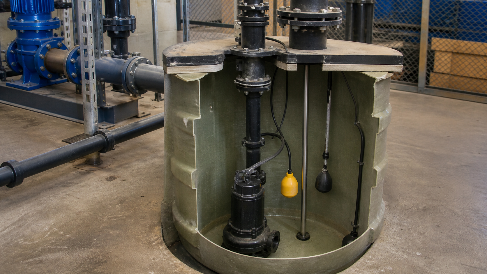
Wastewater from a residence or facility enters a small basin installed below the elevation of the distant sewer main. Gravity alone cannot lift the flow up the slope or across a long horizontal run to reach the collection system. A grinder pump solves this elevation problem by cutting solid waste into a slurry and pressurizing the mixture through a small-diameter force main to the connection point.
A grinder pump is a submersible wastewater pump with a cutting mechanism ahead of the impeller. The cutting assembly reduces toilet paper, human waste, and small debris to fine particles, allowing the slurry to travel through piping smaller than what standard sewage pumps require. The pump then generates enough pressure to overcome the static lift and friction losses between the basin and the sewer tie-in. This combination of maceration and pressure delivery distinguishes the grinder pump from standard sewage pumps, which pass larger solids through open impellers but require bigger piping and lower discharge heads.
Key Takeaways
- A grinder pump cuts wastewater solids to a fine slurry before pressurizing the flow through small-diameter piping to a remote sewer connection.
- The basin, submersible motor, cutter assembly, centrifugal impeller, discharge check valve, and level controls form the complete pumping system.
- Grinder pumps suit low-pressure sewer networks where multiple homes or buildings connect to a shared collection main via individual force mains.
- Application limits include maximum total dynamic head, minimum basin volume for acceptable cycle time, and prohibited materials such as grease, wipes, and fibrous waste.
- Maintenance responsibilities and alarm response protocols must be clear before installation, especially in private residential systems where the property owner operates the equipment.
- Always verify the manufacturer pump curve, system curve, basin inflow rate, and electrical supply against site conditions before final selection.
A Grinder Pump Cuts Solids before Pressurizing Wastewater
The cutting mechanism sits at the pump inlet. Rotating blades or a cutter plate intercept incoming solids and shear them against a stationary ring or screen. The resulting particle size depends on the gap between moving and fixed components. This fine maceration allows the slurry to pass through the impeller without clogging and travel through piping that would otherwise block with intact waste.
After maceration, the impeller adds kinetic energy to the slurry. The volute casing converts velocity to pressure, generating the head needed to lift the flow and overcome pipe friction. Grinder pump models deliver a range of total dynamic heads depending on the pump curve and motor size. By contrast, a standard sewage pump with a non-clog impeller passes larger solids but produces lower discharge pressure and requires larger piping.
The small-diameter force main reduces excavation depth, trench width, and material cost. A pressure pipe can follow terrain contours and avoid deep burial, making low-pressure sewer systems practical in rolling or rocky ground where gravity sewers would require extensive excavation or lift stations. The tradeoff is that the system depends entirely on the pump; a power failure or mechanical breakdown stops wastewater conveyance until service is restored.
Inside the Basin, Motor, Cutter, Impeller, and Controls
The basin holds wastewater inflow between pump cycles. Volume is sized so the pump runs at an acceptable frequency under peak flow. A concrete, fiberglass, or polyethylene tank sits below grade with an access cover at ground level. The basin must remain watertight to prevent groundwater infiltration and provide adequate submergence over the pump inlet to avoid air entrainment.
The submersible motor drives both the cutter and impeller. Continuous-duty motors rated for wastewater service include thermal overload protection that shuts the motor down if winding temperature exceeds the safe limit, with automatic reset once it cools. The motor shaft extends downward to the cutter assembly, then continues to the impeller.
The cutter assembly consists of rotating blades on the pump intake and a stationary cutter ring or bar. As wastewater enters, centrifugal force draws solids toward the rotating element, where they are sheared into small particles. The impeller sits immediately downstream of the cutter. Closed or semi-open impellers accelerate the slurry and discharge it into the volute. The casing directs flow to a threaded or flanged discharge connection, where a check valve prevents backflow when the pump stops.
Level controls start and stop the pump. Float switches, pressure transducers, or capacitance probes sense the liquid level in the basin. When wastewater rises to the start level, the controller energizes the motor. The pump runs until the level drops to the stop point, then shuts off. A high-level alarm activates if the basin continues to fill beyond the start level, signaling a pump failure, clogged discharge line, or excessive inflow. The alarm may trigger an audible horn, a light, or a remote telemetry signal depending on system design.
The Pumping Cycle from Inflow to Discharge
Wastewater flows by gravity from the building drain into the basin. The liquid level rises until it reaches the start setpoint. The level controller closes the motor contactor, and the pump starts. Inrush current during startup may be several times the running current, so branch circuit sizing and motor protection must account for this transient.
The cutter assembly engages immediately, macerating any solids present at the inlet. The impeller begins to accelerate the slurry, and discharge pressure builds against the closed check valve. Once pressure exceeds the static head in the force main plus the cracking pressure of the check valve, the valve opens and flow enters the piping. The pump continues to run, drawing down the basin at a rate equal to the pump flow minus any ongoing inflow from the building.
When the liquid level drops to the stop setpoint, the controller opens the contactor and the motor shuts off. The impeller coasts to a stop while residual pressure in the force main closes the check valve, preventing backflow into the basin. The cycle repeats as inflow refills the basin. Cycle time and frequency depend on the basin volume, inflow rate, and pump capacity. Short cycles increase motor starts per hour and reduce equipment life.
If the pump cannot keep pace with inflow—due to a clogged discharge line, worn impeller, or excessive demand—the level continues to rise past the start point. The high-level alarm activates, alerting the operator to investigate. Without intervention, the basin will eventually overflow through the access cover or a relief vent, discharging untreated wastewater at grade.
Grinder Pumps in Low-Pressure Sewer Systems
Low-pressure sewer systems distribute wastewater collection across individual grinder pumps rather than relying on a large municipal lift station. Each home or building has a grinder pump and basin on the property. The pump discharges into a private force main that connects to a shared collection line, often a small-diameter pipe laid in a shallow trench along the street or easement. The collection main slopes toward a gravity sewer or treatment plant, with enough grade to drain when pumps are idle and sufficient capacity to handle peak coincident flow when multiple pumps operate simultaneously.
This architecture suits low-density developments, hilly terrain, high groundwater, bedrock, or areas where extending a gravity sewer would require deep excavation or environmental disturbance. Capital cost is lower than a gravity system because trenches are shallow and pipe diameters are small. However, each property owner typically maintains their own pump, basin, and service lateral, shifting long-term operation and repair costs from the utility to the homeowner. Utility policies vary; some municipalities own and service all grinder pumps, while others treat them as private infrastructure.
Hydraulic design requires careful attention to pressure profile and flow diversity. The system curve includes static lift from the lowest basin to the highest discharge point, plus friction losses in the force main. Each pump must generate enough head to overcome this system resistance at its rated flow. Because not all pumps run at once, designers apply a diversity factor to estimate peak simultaneous demand. The collection main must remain below the pressure rating of the pipe and fittings, and air release valves are needed at high points to prevent vapor lock.
Where a Grinder Pump Fits and Where It Does Not
A grinder pump is appropriate when wastewater must be lifted or conveyed under pressure and the solids load consists of typical domestic waste. Single-family homes, small commercial buildings, restrooms in parks or recreational facilities, and remote structures without access to gravity sewers are common applications. The pump handles toilet paper, human waste, and minor food particles from kitchen sinks. It is not designed for industrial process waste, stormwater, high-temperature discharge, or materials that resist cutting.
Grinder pumps do not belong in applications with grease, cooking oil, latex paint, solvents, disposable wipes (even those labeled flushable), sanitary products, dental floss, or fibrous materials such as rags or mop strings. These substances clog the cutter, wrap around the shaft, or accumulate in the basin and force main. Grease solidifies in the piping, reducing flow area and increasing friction losses until the system fails. Wipes do not break down like toilet paper and form blockages at the cutter or check valve.
Where solids are too large or abrasive for a grinder pump—such as industrial facilities with metal shavings, grit, or coarse debris—a sewage pump with a larger solids-passage impeller and bigger piping is more reliable. Where lift is minimal and pipe diameter is not constrained, an effluent pump after a septic tank may be simpler and less expensive. Where the building is above the sewer main and gravity flow is possible, a grinder pump is unnecessary cost and complexity.
System geometry also sets boundaries. If total dynamic head exceeds the pump’s maximum rated head, the pump will not deliver any flow. If the force main is too long or too small in diameter, friction losses will exceed the available head and flow will be insufficient. If the basin is too small, the pump will cycle excessively and overheat. If electrical service is unreliable or single-phase power is unavailable, the system cannot operate. Each of these conditions must be verified during design.
Capacity, Head, Solids, Alarm, and Power Considerations
Capacity must match or exceed peak wastewater flow from the building. Check the manufacturer flow-head curve at the system operating point; do not rely on nameplate free-flow capacity, which applies only at zero head.
Head is the sum of static lift and friction losses. Static lift is the vertical distance from the pump discharge centerline to the highest point in the force main. Friction loss is calculated using the Darcy-Weisbach or Hazen-Williams equation for the pipe diameter, length, roughness, flow rate, and fluid properties. Add minor losses for fittings, valves, and the check valve. The total dynamic head at the design flow must fall within the pump’s operating envelope.
Solids passage depends on the cutter gap and particle-size reduction. The impeller and discharge piping must pass the macerated particles without clogging. If the waste stream includes materials that resist cutting—fibrous rags, rubber, or hard plastics—the cutter will stall or the motor will overload. User education is critical; the property owner or facility manager must understand what can and cannot enter the system.
Alarm systems must alert the responsible party when the high-level condition occurs. In a residential installation, an audible alarm and visual light panel inside the home is standard. In a remote or unstaffed facility, a telemetry link to a central monitoring station or a cellular dialer provides notification. The alarm must be tested during commissioning and periodically thereafter to confirm function.
Electrical supply must provide the correct voltage, phase, and overcurrent protection. The branch circuit must be sized for the motor full-load current plus a safety factor, and the overcurrent device must allow inrush current without nuisance tripping. Ground-fault protection is required for personnel safety. The control panel should be weatherproof, accessible, and labeled with emergency contact information.
Ownership and Maintenance Questions before Installation
Before a grinder pump is installed, establish who owns the equipment, who performs routine maintenance, and who responds to alarms and failures. In municipal low-pressure sewer systems, some utilities own and maintain all grinder pumps as public infrastructure, while others require the property owner to purchase, operate, and repair the pump at their expense. Clarify this responsibility in writing before construction begins.
Routine maintenance includes periodic inspection of the basin for sediment accumulation, checking the alarm function, and verifying that the discharge check valve is not leaking. The manufacturer service manual specifies inspection intervals, which vary by model and application. Some manufacturers recommend removing the pump at intervals to inspect the cutter and impeller for wear, clean the motor cooling passages, and test the seal.
Alarm response must be immediate. A high-level alarm means the system is near overflow. The operator should check the control panel for error codes, verify power to the pump, listen for motor noise, and inspect the discharge line for blockages or valve closure. If the cause is not obvious, a service technician with the proper tools and training should be called. Discharging untreated wastewater to the surface is a public health and environmental violation.
Spare parts availability and local service support affect long-term reliability. Choose a manufacturer with an established distribution network and stocked parts in the region. Verify warranty terms, including what failures are covered and whether on-site service is included. For critical facilities, consider a standby pump or redundant system to maintain service during repairs.
Training the property owner or facility staff is essential. They must know what materials are safe to discharge, how to recognize an alarm condition, how to silence a nuisance alarm, and who to contact for service. Provide written operating instructions and emergency contact numbers at the control panel and inside the building.
FAQs
Can a grinder pump handle a garbage disposal?
A garbage disposal generates food particles, grease, and starchy waste that can accumulate in the basin and clog the cutter or discharge line. Most grinder pump manufacturers advise against garbage disposals in systems with grinder pumps. If a disposal is already installed, limit use to small quantities of soft food waste, run cold water during and after grinding, and inspect the basin more frequently. Grease and coffee grounds are particularly problematic and should not enter the system.
How much does it cost to replace a grinder pump?
Replacement cost depends on the pump model, basin condition, site access, and regional labor rates. If the utility owns the pump, replacement may be covered under their maintenance program. If the property owner is responsible, consult local suppliers for current pricing and budget for eventual replacement when the pump reaches end of life.
What happens if the power goes out?
The grinder pump stops running and wastewater accumulates in the basin. Basin capacity provides temporary storage, but once full, no additional wastewater can enter. Users must reduce water consumption until power is restored. If an extended outage is expected, arrange for temporary pumping or sanitary facilities. Backup power from a generator or battery system can maintain pump operation during outages, but the installation must comply with electrical codes and include proper transfer switching.
Do grinder pumps require special piping materials?
The force main must withstand the discharge pressure, resist corrosion from wastewater, and provide a smooth interior surface to minimize friction losses. PVC, HDPE, and ductile iron are common materials. The pipe must be pressure-rated, not drain-waste-vent (DWV) pipe, and joints must be watertight. Use long-radius elbows to reduce head loss and avoid sharp bends that trap solids or air.
Can two buildings share one grinder pump?
Hydraulically, a single grinder pump can serve multiple buildings if the total flow and head remain within the pump’s capacity. However, shared ownership complicates maintenance and cost allocation. If one property generates excessive flow or discharges prohibited materials, both properties suffer. Separate pumps for each building provide clear responsibility and allow independent operation. If a shared system is unavoidable, document the cost-sharing agreement, maintenance obligations, and dispute resolution process in a recorded easement or homeowners association rules.
Conclusion
A grinder pump solves wastewater conveyance where gravity flow is not possible by cutting solids and pressurizing the slurry through small-diameter piping. Proper application requires verifying the manufacturer pump curve against the system curve, confirming that the basin volume supports acceptable cycle frequency, ensuring that users understand what materials are prohibited, and establishing clear ownership and maintenance responsibilities before installation. Begin selection by calculating total dynamic head, peak flow rate, and duty point; then confirm electrical supply and alarm notification strategy with the site conditions and applicable codes.