
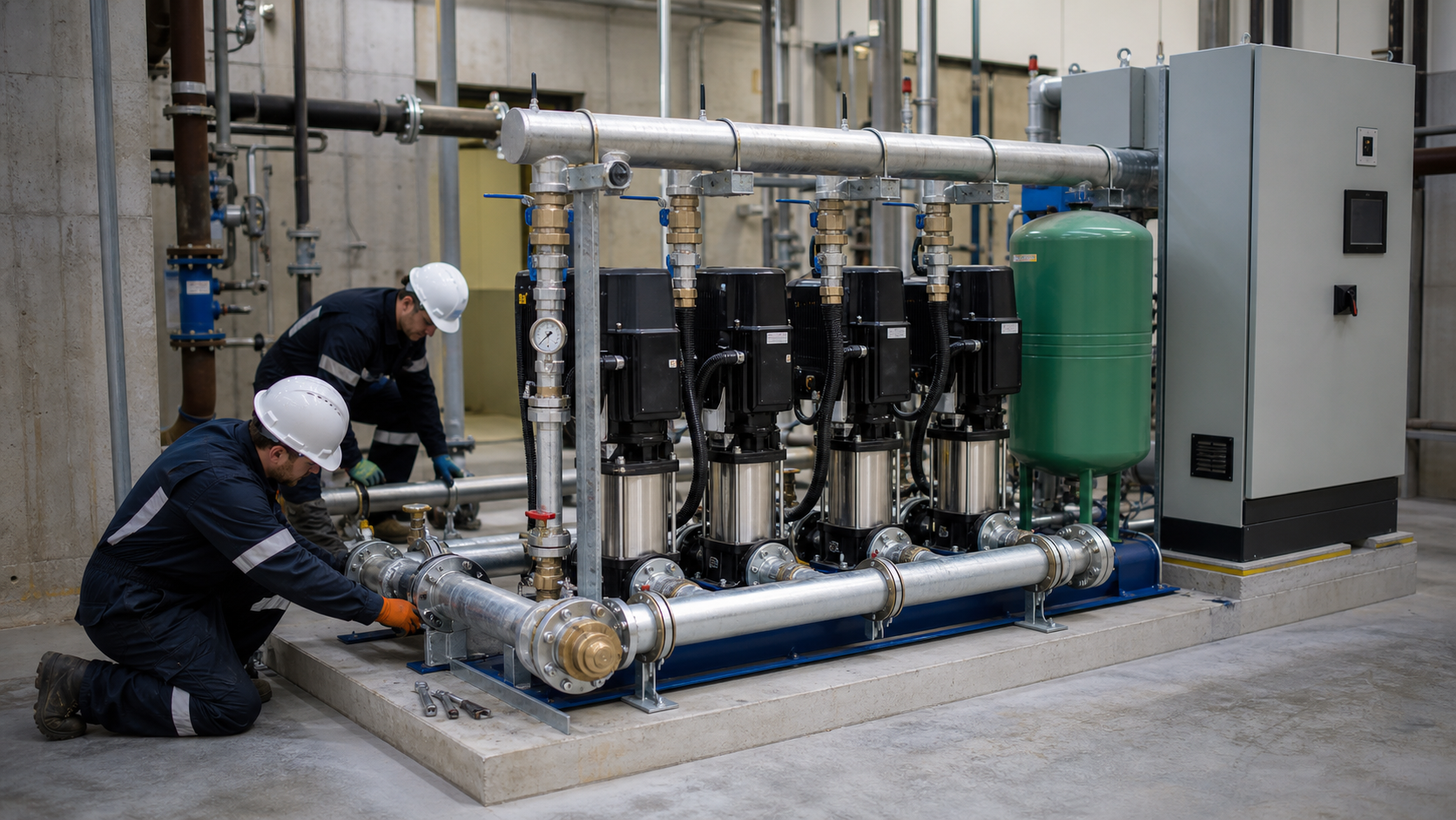
A booster pump installation begins when equipment arrives on site. Before welding pipe or connecting power, verify that the delivered pump matches the specified duty point, the foundation can support operating loads, and suction and discharge piping will not impose strain on pump nozzles. Each verification step prevents a category of failure: mismatched equipment wastes project budget, inadequate foundations allow vibration damage, and piping strain destroys mechanical seals. This article walks through the installation sequence from receipt inspection to final commissioning records.
Key Takeaways
- Verify nameplate duty point, motor rating, and rotation direction against purchase order and system curve before unpacking lifting equipment.
- Design foundation and pipe supports to isolate pump vibration from adjacent structures while preventing suction or discharge nozzles from carrying pipe weight.
- Fill and vent suction line completely, then hand-rotate shaft to confirm freedom of movement before applying power.
- Record baseline vibration, bearing temperature, pressure, flow, and power draw during first run so future measurements detect deterioration.
- Commission control logic by simulating low-pressure, high-pressure, and dry-run faults to confirm system shuts down safely.
Confirm the Duty, Site, and Delivered Equipment
Open the purchase order and compare nameplate data against specified flow rate, total dynamic head, and liquid properties. A booster pump selected for 50 m³/h at 40 m head with clean water will fail if the actual system requires 60 m³/h or contains abrasive solids. The pump curve shipped with the unit shows the operating envelope; confirm your duty point falls within the published range and near best efficiency point (BEP). Operating far from BEP reduces service life through increased vibration and radial thrust on bearings.
Check motor nameplate voltage, phase, and frequency. A 460 V three-phase motor will not run on 380 V supply without a step-up transformer, and a 50 Hz motor will overspeed and overload on 60 Hz power. If a variable frequency drive (VFD) is specified, confirm motor insulation is rated for inverter duty; standard motors may suffer winding failure from voltage spikes at drive output.
Rotate the shaft by hand before lifting the pump. If the shaft binds or drags, internal clearances are incorrect or foreign material entered during shipment. Do not force rotation. Remove casing inspection cover and examine impeller and wear rings for shipping damage. Replace damaged parts before installation begins.
Inspect baseplate, anchor bolts, and grouting instructions. A fabricated steel baseplate must be flat within the tolerance stated in the installation manual. Warped baseplates prevent proper alignment between pump and driver.
Foundation, Access, Drainage, and Vibration Isolation
A booster pump installation transfers dynamic loads into supporting structure. The foundation must be massive enough to absorb vibration without resonance and rigid enough to maintain alignment under operating loads. Foundation mass and dimensions are determined by soil bearing capacity, mounting configuration, pump mass, and operating speed. Consult the installation manual for minimum foundation specifications.
Cast a reinforced concrete pad of adequate thickness, extending beyond baseplate perimeter on all sides per the installation drawing. Allow concrete to cure per structural design requirements before grouting baseplate. Locate foundation where access allows motor removal and bearing replacement without dismantling piping. Vertical clearance above motor must accommodate lifting height of largest component plus rigging equipment.
Install vibration isolators between baseplate and foundation only if the pump sits on elevated floor or near noise-sensitive areas. Spring isolators attenuate pump vibration when properly sized, but they complicate alignment and require flexible suction and discharge connections to avoid transmitting pipe loads back into baseplate. If isolators are used, ensure piping system includes expansion joints or flexible couplings near each pump nozzle.
Provide a floor drain near pump location. Mechanical seal leakage, vent valve discharge, and pressure relief valve flow must drain to sump or collection point without creating slip hazard. If pumped liquid is hazardous or corrosive, drain must route to treatment system rather than general sewer.
Suction and Discharge Piping without Nozzle Strain
Piping strain is a leading cause of premature mechanical seal and bearing failure in booster pump installations. When suction or discharge piping hangs from pump nozzles, thermal expansion and pipe weight create bending moments that deflect shaft and open gaps in seal faces. The installation must support every pipe independently and allow thermal movement without transferring loads to the pump.
Size suction pipe to keep entrance velocity low enough to preserve available net positive suction head (NPSHa). Higher velocities reduce NPSHa and may trigger cavitation even when static submergence is adequate. Route suction pipe with continuous rise toward pump to prevent air pockets. If an elbow is unavoidable near the suction nozzle, orient it so flow approaches pump from the side rather than from below; this reduces swirl and improves flow distribution at impeller eye.
Support suction and discharge piping at intervals that prevent excessive sag per the pipe manufacturer’s structural rating. Each support must carry weight of pipe, fittings, valves, and contained liquid without deflecting beyond the allowed tolerance under full load. Hangers and brackets must not restrain thermal expansion; use sliding supports or spring hangers that allow axial movement while preventing vertical or lateral displacement.
Install flexible connectors or expansion joints immediately adjacent to pump nozzles if piping system cannot be routed to accommodate thermal growth. A flexible connector absorbs axial movement and angular misalignment within its rated range, but it must be anchored on far side to prevent pressure thrust from pushing pump off baseplate. Anchor discharge pipe at first rigid support downstream of flexible connector, and design that anchor to withstand full pressure thrust force:
F = P × A
where F is thrust force in newtons, P is maximum operating pressure in pascals, and A is internal cross-sectional area of pipe in square meters. For a hypothetical 100 mm diameter pipe at 6 bar (600 kPa), thrust is approximately 4,700 N.
Before tightening flange bolts at pump nozzles, place straightedge across flange faces and check for gap or offset. If flanges do not meet evenly with hand pressure, adjust pipe supports until both flanges align, then torque bolts in star pattern to gasket manufacturer specification.
Check Valves, Isolation Valves, Sensors, and Pressure Tank
The booster pump system requires control components that prevent backflow, isolate pump for maintenance, measure operating conditions, and stabilize pressure during demand fluctuations. Each component must be located and oriented correctly to perform its function without introducing additional head loss or flow disturbance.
Install spring-loaded check valve on discharge line near pump outlet. The check valve prevents reverse flow when pump stops, protecting impeller from backward rotation and water hammer. Select check valve with cracking pressure low enough that it opens fully at minimum flow but high enough to close before reverse flow begins. Consult valve manufacturer data to match cracking pressure to pump operating range. Silent check valves with assisted closing mechanisms reduce water hammer but cost more than swing check valves.
Place gate valve or ball valve on both suction and discharge sides of pump. These isolation valves allow pump removal for service without draining entire system. Suction valve must be fully open during operation; throttling suction valve to reduce flow will lower NPSHa and may cause cavitation. If flow control is required, throttle discharge valve or use VFD to reduce pump speed.
Mount pressure sensors at pump discharge and system delivery point. Discharge pressure measurement provides input to control system; drop below setpoint triggers pump start, and rise above upper limit signals pump stop. Delivery-point sensor detects whether booster system maintains required pressure at farthest or highest fixture. If the two pressures differ by more than calculated friction loss in interconnecting pipe, a restriction or leak exists between pump and delivery point.
If booster system serves intermittent demand—for example, building water supply—install hydropneumatic pressure tank on discharge manifold. The tank provides buffer volume that prevents pump from cycling on and off with every small draw. Size tank to provide adequate runtime per cycle based on pump power and system demand profile. Short-cycling reduces motor life and wastes energy on repeated startup currents.
Electrical Supply, Earthing, Drives, and Control Logic
Electrical installation must comply with local codes and motor manufacturer wiring diagram. Supply voltage should remain within the motor nameplate tolerance at full load, typically ±10% of nominal voltage. Voltage drop in feeder cables reduces motor torque and increases current draw, leading to overheating and nuisance trips on overload relay. Measure voltage at motor terminals under load; excessive voltage drop requires larger cable or relocated distribution panel.
Connect motor frame to site earthing system using conductor sized according to local electrical code. Proper earth connection provides low-impedance path for fault current, allowing overcurrent protection devices to operate quickly and reducing shock hazard. Do not rely on flexible conduit or cable armor as sole earthing path.
If VFD controls motor, install input line reactors or chokes to reduce harmonics injected into supply system. Output reactors between drive and motor limit voltage rise time (dv/dt) and reduce cable-induced motor bearing currents. Program drive acceleration and deceleration ramps to match system inertia; excessively fast ramps cause water hammer and mechanical shock, while excessively slow ramps waste time and energy during startup.
Wire control system so pump starts automatically when discharge pressure falls below lower setpoint and stops when pressure rises above upper setpoint. Include pressure switch or transducer with adequate deadband to prevent rapid cycling near setpoint. Control logic must also monitor for fault conditions and shut down pump safely:
- Dry run protection: If suction pressure or flow rate falls below minimum threshold, stop pump. Running dry destroys mechanical seals and bearings rapidly.
- Overload protection: Motor starter or VFD must trip on overcurrent, and control system must prevent automatic restart until fault is cleared and manually reset.
- High discharge pressure: If discharge pressure exceeds maximum rating of pump casing or system components, stop pump and close motorized isolation valve if fitted.
Test each interlock by simulating fault condition before commissioning system. Disconnect suction supply and verify dry-run sensor stops pump. Close discharge valve fully and confirm high-pressure cutoff trips before relief valve opens.
Fill, Vent, Rotate, and Start the System
A booster pump cannot self-prime unless specifically designed with priming chamber and check valve. Before first start, fill suction line and pump casing completely with liquid and vent all air pockets. Trapped air reduces NPSHa, creates noise and vibration, and may prevent pump from developing full pressure.
Close discharge valve and open suction isolation valve. Open vent plug at highest point on pump casing—usually at top of volute—and allow liquid to flow from suction supply until steady stream free of bubbles emerges from vent. If suction supply is below pump centerline, fill suction line from external source or use vacuum pump to evacuate air before opening suction valve. Do not assume opening valve will pull liquid upward; centrifugal pumps lose prime instantly when air enters.
After venting, close vent plug and rotate pump shaft by hand through at least two full revolutions. Shaft should turn smoothly with consistent resistance. If shaft locks or grinds, stop immediately and investigate. Possible causes include bearing contamination, seal face contact from piping strain, or foreign objects inside casing.
With discharge valve still closed, energize motor briefly then stop. Observe rotation direction by comparing shaft movement to arrow cast into pump casing. If motor rotates backward, pump will develop no pressure and may suffer hydraulic shock when stopped. Reverse rotation by swapping any two phase conductors at motor terminal box. Do not reverse rotation by changing drive settings; motor winding connections must produce forward rotation at line frequency.
Open discharge valve slowly while monitoring discharge pressure gauge. Pressure should rise smoothly as valve opens. If pressure surges or pump vibrates excessively, close valve slightly and allow system to stabilize before continuing. Run pump at design flow rate and listen for unusual noise. Cavitation produces crackling or gravel-like sound; rubbing or scraping indicates internal contact between rotating and stationary components.
Commissioning Tests and Baseline Records
Commissioning establishes baseline performance that future measurements will be compared against. Record operating conditions during first stable run so wear, fouling, and component degradation can be detected early.
Measure and record:
- Flow rate using calibrated flow meter or bucket-and-stopwatch test at known outlet
- Suction pressure at pump inlet flange
- Discharge pressure at pump outlet flange
- Total dynamic head calculated as discharge pressure minus suction pressure, converted to meters of liquid column
- Motor current on all three phases
- Power consumption using power meter or calculated from voltage, current, and power factor
- Vibration amplitude at motor and pump bearing housings in radial and axial directions, measured in mm/s RMS
- Bearing temperature using infrared thermometer or contact sensor after continuous operation
- Liquid temperature at suction and discharge points
Compare measured flow and head to pump curve. Operating point should fall within the tolerance band shown on the curve. If flow is lower than expected, check for restriction in discharge line, partially closed valve, or undersized piping. If flow is higher than expected and discharge pressure is lower, confirm system curve matches design assumptions; additional flow paths or lower-than-expected friction losses will shift operating point to right on pump curve.
Calculate wire-to-water efficiency by dividing hydraulic power by electrical power input:
η_system = (ρ × g × Q × H) / P_elec
where ρ is liquid density in kg/m³, g is gravitational acceleration (9.81 m/s²), Q is flow rate in m³/s, H is total dynamic head in meters, and P_elec is electrical power in watts. For a hypothetical booster pump operating at 50 m³/h (0.0139 m³/s) and 40 m head with clean water (ρ = 1000 kg/m³), hydraulic power is approximately 5.45 kW. If motor draws 8 kW, system efficiency is 68%, which includes motor and drive losses.
Vibration should remain below limits specified in ISO 10816 for the pump mounting configuration. Bearing temperatures should stabilize below the motor manufacturer’s maximum rating. Higher temperatures indicate inadequate lubrication, misalignment, or bearing damage.
File commissioning record with installation drawings and original pump curve. Schedule follow-up measurements per the maintenance manual or operating environment severity.
FAQs
Can I install a booster pump on the discharge side of an existing pump?
Yes, if the system requires pressure higher than a single stage can provide. The second pump must be rated for discharge pressure of first pump as its suction pressure. This series arrangement multiplies head but does not increase flow. Confirm intermediate piping and second pump casing are rated for combined discharge pressure of both pumps. Install pressure relief valve between pumps set to open below casing rating of downstream pump.
What happens if I start the pump with the discharge valve closed?
The pump operates at shutoff head, where flow is zero and pressure is maximum. Power consumption drops because no hydraulic work is being done, but liquid inside casing recirculates and heats rapidly. Temperature rise can damage mechanical seals and cause liquid to vaporize, leading to cavitation. Do not run at shutoff beyond the time limit stated in the pump manual unless pump includes minimum-flow bypass or thermal relief valve.
How do I prevent water hammer when the pump stops?
Install slow-closing check valve on discharge line and program VFD to decelerate gradually if variable speed control is used. Water hammer occurs when fluid column decelerates too quickly, creating pressure spike that propagates through piping system. Pressure surge magnitude is proportional to rate of velocity change. A check valve that closes gradually rather than slamming shut reduces peak pressure substantially.
Should I oversize the motor to handle future increases in system demand?
No. Motors operate most efficiently near rated load. An oversized motor draws higher no-load current and operates at lower power factor, wasting energy and increasing electricity costs. If future demand may exceed current pump capacity, specify VFD and program it to limit speed to level required by current system. When demand increases, raise maximum speed setting rather than replacing motor.
How often should I inspect the mechanical seal and bearings?
Inspect mechanical seal during initial operation by checking for visible leakage around seal housing. A properly functioning seal may seep slightly during first few hours of operation as faces lap in, but continuous dripping or pooling indicates a problem. Bearing inspection intervals depend on operating environment and duty cycle. Consult the maintenance manual for recommended intervals based on service conditions. For continuous-duty pumps or pumps handling abrasive or corrosive liquids, increase inspection frequency.
Conclusion
A successful booster pump installation confirms delivered equipment matches specified duty, supports pump without imposing nozzle strain, vents all air from suction line, verifies correct rotation before applying full power, and records baseline measurements during first stable run. The commissioning record becomes reference for future performance monitoring; deviation from baseline vibration, temperature, pressure, or current signals wear or fouling before catastrophic failure occurs. Before energizing the system, review control logic by simulating each fault condition and confirming pump stops safely.