
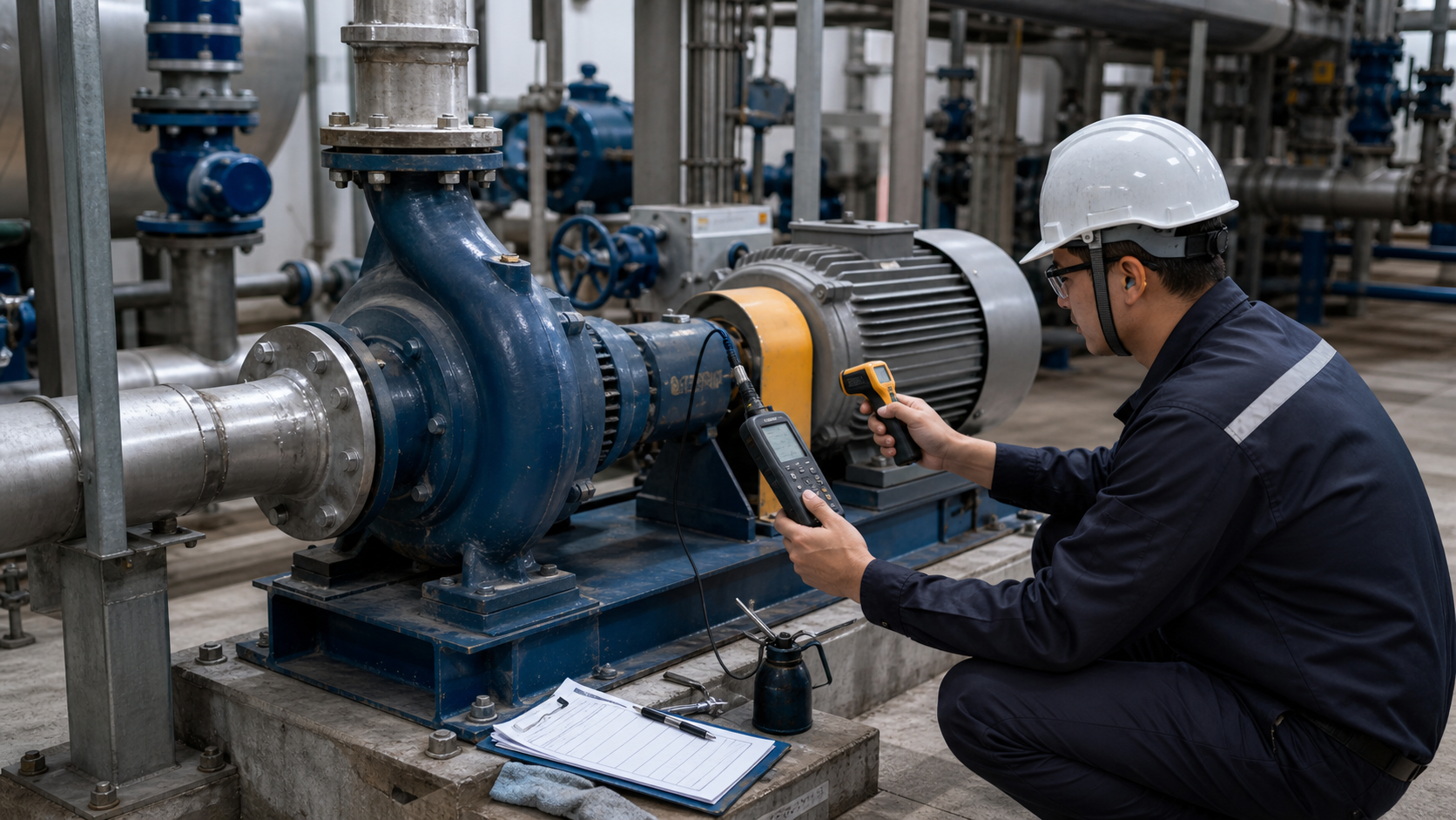
Record flow, pressure, power, vibration, and bearing temperature at the duty point before the first fault appears. These baseline measurements turn maintenance from reactive repair into scheduled inspection, letting you detect seal wear, bearing degradation, and alignment drift while parts remain serviceable.
Key Takeaways
- Capture commissioning data—discharge pressure, suction pressure, motor current, bearing temperature, vibration—to establish the normal operating signature for future comparison.
- Daily checks cover seal leakage, bearing temperature, noise, and vibration; lubrication levels and alignment verification follow manufacturer intervals; performance tests against the pump curve track efficiency trends.
- Monitor bearing temperature rise above ambient, seal flush flow, and vibration velocity to detect wear, misalignment, or hydraulic instability before components fail.
- Schedule wet-end inspections during process shutdowns to measure impeller clearance, wear ring gap, casing erosion, and shaft runout, replacing parts when wear exceeds manufacturer tolerances.
- Log every inspection, measurement, and corrective action in a pump-specific record to track degradation rates and adjust intervals based on actual conditions.
Record the Baseline before Setting Intervals
After installation, commissioning, or rebuild, operate the pump at design flow and record discharge pressure, suction pressure, power draw, bearing housing temperature, seal flush flow, and vibration at motor and pump bearing locations. Use the manufacturer’s certified pump curve to confirm that measured head matches the curve at measured flow. Record ambient temperature, liquid temperature, and specific gravity so future readings can be corrected for process changes.
Vibration measurements should capture velocity in millimeters per second RMS or inches per second RMS in radial, axial, and tangential directions at each bearing. Bearing temperature readings taken with infrared thermometer or embedded RTD should record the rise above ambient rather than absolute temperature—a bearing at 50°C rise in a 20°C room has the same thermal margin as a bearing at 80°C rise in a 50°C environment.
Store this baseline with the pump nameplate information, motor data, system curve, and piping isometric. When performance degrades, compare new measurements to baseline values. A flow reduction at constant speed and system resistance points to impeller wear or internal recirculation; rising power at constant flow suggests increased system resistance or mechanical drag.
Shift and Daily Operating Checks
Operators should inspect running pumps at the start of each shift. Look for visible leakage at the mechanical seal or packing gland, listen for cavitation noise or bearing rumble, and feel bearing housings for excessive heat. Check discharge pressure and compare it to the expected value for current flow. A sudden pressure drop with no change in valve position indicates a system leak, impeller damage, or loss of prime.
Mechanical seal leakage rates vary by design and service. A steady drip from a packed stuffing box is normal packing operation; a stream or spray indicates adjustment needs or seal failure. For mechanical seals, any visible leakage beyond occasional moisture should trigger investigation of flush flow, seal faces, or O-ring condition.
Bearing housing temperature should remain stable. A rise over several days, even if below the absolute limit specified in the bearing or pump manual, signals deteriorating lubrication, misalignment, or bearing wear. Record temperatures at the same location under similar load conditions to make trends meaningful.
Vibration checks using handheld analyzer or fixed sensors should be compared to baseline values. Increasing vibration amplitude often indicates looseness, imbalance, misalignment, or bearing wear. Sudden increases at running-speed multiples point to specific faults: imbalance shows at 1× running speed, misalignment at 2× and 3×, bearing defects produce high-frequency spikes.
Lubrication, Bearings, Seals, and Leakage
Bearing lubrication intervals depend on bearing type, speed, load, and environment. Consult the bearing or pump manufacturer’s maintenance manual for regreasing frequency and oil change intervals specific to your model. Over-greasing causes churning and temperature rise; under-greasing leads to metal-to-metal contact and spalling.
For grease-lubricated bearings, check housing temperature weekly. For oil-lubricated bearings, check oil level weekly and inspect used oil for metallic particles, discoloration, or emulsification. Metal flakes indicate bearing wear; milky appearance points to water ingress through seals or condensation.
Mechanical seal maintenance focuses on flush flow, seal chamber pressure, and leakage. Single seals typically require clean, cool flush liquid at pressure above the seal chamber to prevent flashing and maintain face lubrication—consult the seal manufacturer’s data sheet for the required differential. Dual seals use barrier fluid in the outer chamber; monitor barrier fluid level, pressure, and temperature. A rapid drop in barrier fluid level signals inner seal failure.
Seal Flush and Bearing Lubrication Checks
Component | Check Frequency | Service Interval | Condition Trigger |
|---|---|---|---|
Grease bearings | Weekly temperature | Per manufacturer manual | Temperature rise from baseline |
Oil bearings | Weekly level, monthly sample | Per manufacturer manual | Metallic particles, water contamination |
Mechanical seal flush | Daily flow indicator | Continuous during operation | Flow loss, pressure drop below required differential |
Packing gland | Every shift | Adjust when leakage exceeds design drip rate | Stream or spray leakage |
Stuffing box packing requires periodic adjustment. Tighten gland nuts incrementally—typically one-quarter turn at a time—until leakage reduces to the specified drip rate, then back off slightly to prevent overheating. Replace packing when adjustment no longer controls leakage or when the shaft sleeve shows scoring.
Coupling, Alignment, Foundation, and Pipe Strain
Shaft alignment between pump and driver must be checked during installation, after bearing replacement, and at intervals specified in the pump or coupling manual. Misalignment causes excessive bearing load, seal failure, and vibration. Acceptable alignment tolerances vary by coupling type, pump speed, and bearing design—consult the coupling manufacturer for angular and parallel offset limits applicable to your installation.
Check alignment at the intervals your equipment manufacturer recommends. Measure angular and parallel misalignment using dial indicators or laser alignment tools. Elastomeric couplings tolerate more offset than rigid or gear couplings, but precision alignment practices minimize wear on all types.
Foundation condition affects alignment stability. Inspect grout under the baseplate for cracks, voids, or looseness. A hollow sound when tapping the baseplate indicates lost grout support. Loose anchor bolts allow the pump to shift during operation. Retorque anchor bolts to specification after the initial run-in period stated in the installation manual and at regular intervals thereafter.
Pipe strain transfers external loads into the pump casing, distorting alignment and stressing the casing and nozzles. Suction and discharge flanges should mate without forcing. If flange bolts require significant persuasion to align holes, the piping imposes strain. Support piping independently near the pump, allowing flanges to mate with finger-tight bolts before final torquing. After tightening all pipe connections, recheck shaft alignment; a change indicates pipe strain that must be corrected with additional pipe supports or repositioned hangers.
Flow, Head, Power, Vibration, and Temperature Trends
Periodic performance testing compares current operation to baseline data and the manufacturer’s pump curve. The test interval should align with your maintenance program and process requirements. Measure flow using an existing flowmeter or differential pressure across an orifice or venturi. Record suction and discharge pressure with calibrated gauges at the pump nozzles, correcting to the pump centerline if gauges are located elsewhere. Measure motor current and power factor, or use a power meter to capture electrical input.
Calculate total dynamic head:
TDH = (P_discharge – P_suction) × 2.31 / SG + Z_discharge – Z_suction
where P is pressure in psig, SG is specific gravity, and Z is elevation in feet. For SI units:
TDH = (P_discharge – P_suction) / (ρ × g) + Z_discharge – Z_suction
where pressures are in pascals, ρ is density in kg/m³, g is 9.81 m/s², and elevations are in meters.
Plot the measured flow and head point on the pump curve. If the point falls significantly below the curve, internal wear or recirculation is degrading performance. Compare electrical input to baseline; power increase at constant flow indicates mechanical friction, misalignment, or added system resistance.
Efficiency trends provide early warning of wear. Pump efficiency is:
η_pump = (ρ × g × Q × TDH) / P_shaft
where Q is flow in m³/s, TDH is in meters, and P_shaft is mechanical power in watts. A sustained efficiency drop from baseline justifies inspection during the next scheduled shutdown. Use the trend slope and your energy costs to determine when overhaul becomes economically justified.
Vibration trending uses the same measurement points and directions as baseline checks. Record overall vibration velocity and note any new frequency peaks. Progressive increases in 1× running speed amplitude suggest imbalance or looseness; 2× and 3× peaks point to misalignment. Bearing-tone frequencies appear at high multiples of running speed and indicate inner race, outer race, or rolling element defects. Many centrifugal pump maintenance programs now include vibration spectrum analysis to detect bearing faults months before failure.
Temperature monitoring extends beyond bearing housings. Motor winding temperature, measured by embedded thermistors or thermal imaging, should remain within the motor’s rated temperature rise. Liquid temperature at the pump discharge should match process expectations; unexpected heating indicates internal recirculation or mechanical friction.
Planned Shutdown Inspection of Wet-End Parts
Internal inspection requires a process shutdown, pump draining, and disassembly. Schedule wet-end inspections based on service severity and manufacturer recommendations. Clean water service allows longer intervals between inspections; abrasive slurries or corrosive chemicals require shorter intervals. Use performance trends and condition monitoring to adjust the schedule.
After isolating the pump with closed and locked valves, drain the casing and flush with clean water if handling hazardous or contaminated liquids. Remove the coupling guard and disconnect the coupling. Support the motor or remove it to access the pump casing. Remove casing bolts and separate the casing halves or remove the back pullout assembly, depending on pump design.
Inspect the impeller for erosion, corrosion, or impact damage. Measure vane thickness at inlet and outlet; significant thinning reduces head and efficiency. Check the impeller hub fit on the shaft and keyway condition. A loose impeller allows axial movement and rubs the casing.
Measure wear ring clearance with feeler gauges or inside micrometers. Verify new wear ring clearance specification in the pump manual. Clearance growth beyond the manufacturer’s wear limit causes internal recirculation and efficiency loss. Replace wear rings when clearance exceeds that limit.
Examine the casing interior for erosion, especially near the cutwater in volute pumps or the diffuser vanes in multistage pumps. Deep pitting or material loss compromises hydraulic performance and structural integrity. Shaft sleeves under packing or mechanical seals should be smooth and free of grooves; scoring allows leakage past seals and packing.
Check shaft runout by supporting the shaft in V-blocks and rotating it under a dial indicator. Consult the manufacturer’s specification for maximum allowable runout—excessive runout indicates a bent shaft or worn bearings, requiring shaft replacement or straightening.
Reassembly reverses disassembly with attention to gasket surfaces, bolt torque, and alignment. Use new gaskets and O-rings. Torque casing bolts in a star pattern to the manufacturer’s specification to prevent casing distortion. Recheck alignment after reassembly and before reconnecting piping.
Condition-Based Triggers and Maintenance Records
Scheduled intervals provide a baseline, but condition monitoring allows maintenance to respond to actual pump health. Several conditions justify advancing the next inspection or overhaul:
Immediate shutdown triggers:
- Mechanical seal failure with continuous liquid stream
- Bearing temperature exceeding manufacturer limit
- Vibration doubling from baseline or exceeding alarm threshold
- Sudden loss of discharge pressure with no system change
- Loud grinding, knocking, or screeching noise
Advance next inspection:
- Bearing temperature rise significantly above baseline
- Efficiency drop from baseline
- Vibration increase from baseline
- Seal leakage increase requiring frequent makeup
- Visible shaft or coupling movement
Routine inspection as scheduled:
- All parameters stable near baseline
- No new noises or leakage
- Temperature and vibration within normal range
Document every inspection, measurement, and corrective action in a pump-specific log. Record date, operating hours, flow, pressures, power, temperatures, vibration readings, and any abnormalities. Note parts replaced, adjustments made, and reinstallation torque values. Over time, this log reveals degradation patterns and helps optimize inspection intervals.
For critical pumps, maintain a spare rotor assembly and seal to allow rapid replacement during unplanned outages, with the failed assembly repaired offline. Track mean time between failures and mean time to repair to justify inventory decisions and identify chronic issues.
FAQs
How do you maintain a centrifugal pump that runs continuously versus intermittent service?
Continuous-duty pumps accumulate wear hours faster and require shorter intervals between lubrication, alignment checks, and internal inspections. Intermittent-service pumps experience more start-stop cycles, which impose transient mechanical and thermal stress. For intermittent pumps, count both operating hours and start cycles; replace seals and bearings based on whichever limit is reached first according to manufacturer guidance. Continuous pumps benefit from vibration trending and performance testing at fixed hour intervals; intermittent pumps require pre-start inspections and post-shutdown temperature checks.
What maintenance does a centrifugal pump need when handling abrasive slurries or corrosive chemicals?
Abrasive service accelerates wear ring, impeller, and casing wear. Shorten internal inspection intervals and consider hard-facing or ceramic coatings on wear surfaces. Monitor performance more frequently than in clean service, as erosion degrades efficiency quickly. Corrosive chemicals attack seals, gaskets, and metallurgy. Inspect seal faces and O-rings for chemical attack during every shutdown. Maintain flush flow rates to prevent chemical concentration in the seal chamber. Replace elastomers at the first sign of swelling, cracking, or loss of resilience, not at fixed intervals.
Can you extend maintenance intervals by upgrading to better bearings or seals?
Higher-grade bearings, such as ceramic hybrid or sealed-for-life designs, can reduce regreasing frequency or eliminate it, but they do not eliminate the need for temperature and vibration monitoring. Upgrading from packing to a mechanical seal or from a single seal to a dual seal reduces leakage and external maintenance, but seal face inspection and flush system checks remain necessary. Component upgrades improve reliability and reduce maintenance hours per year without eliminating condition monitoring or scheduled shutdowns for internal inspection.
How do you adjust maintenance intervals after a repair or overhaul?
After any invasive repair—bearing replacement, seal change, impeller swap, or realignment—treat the pump as newly commissioned. Capture a new baseline of flow, pressure, power, vibration, and temperature under normal operating conditions. Schedule the first post-repair inspection according to the manufacturer’s run-in recommendation to verify that reassembly was correct and no infant failures occur. If measurements match pre-repair baselines and no new issues appear, return to standard intervals. If performance remains degraded or vibration is higher, investigate assembly errors, worn mating parts, or alignment drift before extending operation.
What tools and instruments are necessary for a complete centrifugal pump maintenance program?
At a minimum, equip the maintenance team with calibrated pressure gauges, an infrared thermometer, a handheld vibration meter, a dial indicator or laser alignment tool, feeler gauges, micrometers, torque wrenches, and an ammeter or power meter. For advanced programs, add vibration spectrum analyzers, ultrasonic thickness gauges for casing wear measurement, and flow measurement capability. Many operations integrate continuous vibration and temperature sensors with SCADA or predictive maintenance software to trend data automatically and generate alerts when parameters exceed thresholds.
Conclusion
A centrifugal pump maintenance program built on baseline measurements, scheduled inspections, and condition-based triggers protects process reliability and extends component life. Start by recording flow, pressure, power, vibration, and temperature while the pump is healthy, then use those values to detect degradation before failure. For pumps operating outside documented tolerances or requiring maintenance interval guidance specific to your installation, gather the baseline data package, current operating conditions, and pump nameplate information for engineering review.