
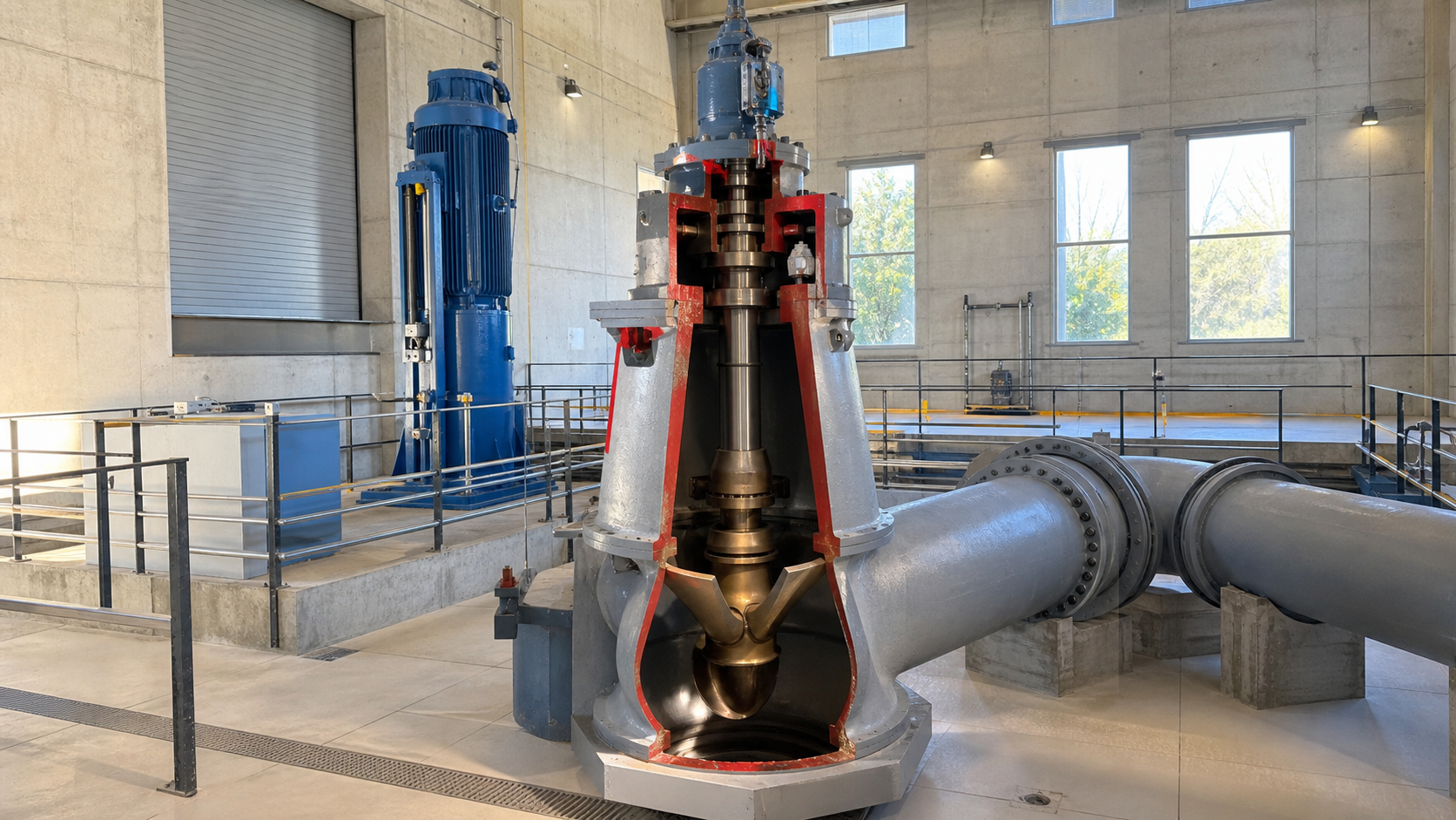
An axial flow pump moves liquid parallel to the shaft axis through a propeller that generates lift. Water enters the intake bell, passes through rotating propeller blades, travels through a vertical column or horizontal casing, and exits through a discharge elbow. The diagram reveals five zones: the intake bell and suction cone that guide flow into the propeller eye, the propeller assembly with hub and blades that add energy, the column pipe that carries flow, the shaft and bearing train that support rotating elements, and the discharge elbow that redirects flow. This arrangement delivers high volumetric flow at low heads—making axial flow pumps the standard choice for flood control, irrigation, cooling water circulation, and raw water intake where system resistance is minimal.
Key Takeaways
- Water moves parallel to the shaft through a propeller that works like an aircraft wing, generating lift rather than centrifugal pressure rise.
- The propeller, column, shaft, bearings, and discharge elbow form a vertical or horizontal assembly optimized for high-flow, low-head service.
- Fixed-pitch propellers offer simplicity; adjustable-pitch designs allow field tuning to match variable system curves without changing motor speed.
- Intake submergence must exceed a manufacturer-specified minimum depth to prevent vortex formation and air entrainment that destroy hydraulic performance.
- Selection requires matching the pump curve to the actual system curve at the duty point, verifying NPSHa against NPSHr, and confirming driver power at the expected operating range.
Read the Axial Flow Pump from Intake to Discharge
Water enters the intake bell at the suction side, where the bell’s flared profile reduces velocity and distributes flow across the propeller diameter. The suction cone inside the bell aligns flow with the propeller eye, minimizing turbulence and swirl that reduce efficiency. As water contacts the propeller blades, each blade acts as an airfoil, generating lift that accelerates flow axially. The propeller hub connects blades to the shaft and rotates at motor speed.
After passing through the propeller, water enters the column pipe—a vertical conduit that encloses the shaft and bearing assembly. Water travels through the column, exiting into a discharge elbow that redirects flow from vertical to horizontal. The elbow must have adequate radius to minimize head loss; sharp bends create turbulence and reduce net capacity.
The shaft runs the full column length, supported by line bearings spaced along the column and a thrust bearing at the discharge head. The motor or driver mounts above the discharge head or at grade level, transmitting torque through the shaft to the propeller. For horizontal axial flow pumps, the column becomes a horizontal barrel, and the shaft orientation follows the barrel axis.
This parallel flow path—intake, propeller, column, discharge—defines the axial flow pump’s efficiency at moving large volumes against low resistance.
Propeller, Hub, Blades, and Tip Clearance
The propeller converts mechanical shaft power into fluid velocity and pressure rise through blade lift. Each blade has an airfoil cross-section with a leading edge, trailing edge, and cambered profile that generates lift as water flows past. Blade angle—the pitch—determines lift magnitude and flow rate at a given speed. Steeper angles produce higher head at lower flow; flatter angles deliver higher flow at lower head.
The hub anchors blades to the shaft and encloses the propeller boss. The hub may be cast integral with fixed-pitch blades or machined to accept adjustable-pitch blade roots.
Tip clearance—the radial gap between blade tips and the column or casing wall—directly affects efficiency. Tight clearances prevent recirculation from the high-pressure discharge side back to the low-pressure suction side. Excessive clearance allows tip leakage that reduces net head and wastes power. As wear increases clearance over time, performance degrades. Inspection records should track tip clearance against the manufacturer’s tolerance.
Blade count varies by application. Fewer blades reduce cost and weight but may increase vibration and noise. More blades distribute load evenly and smooth hydraulic pulsation. The optimal count depends on specific speed—a dimensionless parameter combining flow, head, and speed.
Material selection depends on liquid properties and operating environment. Cast iron and bronze suit clean freshwater. Stainless steel alloys resist corrosion in seawater or chemical service. Composite materials reduce weight in large-diameter propellers but require careful quality control. The manufacturer’s material specification and hardness test records confirm suitability for the intended duty.
Column, Shaft, Bearings, and Driver Arrangement
The column pipe encloses the shaft and provides a conduit for pumped liquid. Column sections bolt together with flanged joints, sealed by gaskets or O-rings. Each section includes bearing supports that position line bearings along the shaft length. Line bearing spacing depends on shaft diameter, speed, and deflection limits specified by the manufacturer. The column must resist internal pressure, external loads from piping, and bending moments from shaft misalignment or hydraulic imbalance.
The shaft transmits torque from the driver to the propeller and resists bending, torsion, and axial thrust. Shaft diameter calculation follows manufacturer-specific procedures based on transmitted power, speed, bearing span, and critical speed. Underdimensioned shafts deflect excessively, causing vibration and premature bearing wear. Field measurements of shaft runout during installation verify straightness within the manufacturer’s tolerance.
Line bearings support radial loads along the shaft. Rubber-lubricated bearings use the pumped liquid as lubricant, eliminating external grease systems. Oil-lubricated bearings require a separate oil supply and drain but handle abrasive liquids that would damage rubber. Bearing wear limits are specified by the manufacturer; excessive clearance allows shaft vibration that damages seals and couplings.
The thrust bearing absorbs axial hydraulic force generated by the propeller. Axial flow propellers produce downward thrust in vertical pumps; the thrust bearing at the discharge head prevents shaft movement. Thrust bearing capacity must exceed the calculated hydraulic thrust plus a margin specified by the bearing manufacturer for transient loads during startup and shutdown. Bearing temperature should remain below the manufacturer’s limit for the specific bearing design and lubricant.
The driver—electric motor, diesel engine, or turbine—mounts at the discharge head or at grade with an intermediate gearbox. Direct-drive arrangements couple the motor shaft to the pump shaft through a flexible coupling that accommodates minor misalignment. Geared drives allow the motor to operate at a different speed than the propeller, optimizing motor efficiency. Motor power must meet or exceed the brake horsepower calculated from the pump curve at the maximum expected operating point, plus the motor manufacturer’s specified service factor.
How Blade Lift Produces High Flow at Low Head
Axial flow pumps generate head through blade lift, not centrifugal force. As the propeller rotates, each blade moves through the water at a tangential velocity determined by shaft speed and blade radius. Water enters the blade at an axial velocity determined by flow rate and propeller area. The combination of tangential and axial velocity creates a relative velocity approaching the blade at an angle of attack.
The blade’s cambered airfoil profile deflects this relative flow, creating higher pressure on the pressure side and lower pressure on the suction side. The pressure difference generates lift perpendicular to the relative velocity. Because the blade is angled, this lift force has an axial component that accelerates water along the shaft axis—increasing velocity and pressure—and a tangential component that resists shaft rotation, requiring input torque.
The velocity triangle at blade inlet and outlet quantifies this energy transfer. At the inlet, absolute velocity equals the vector sum of axial flow velocity and tangential blade velocity. At the outlet, the blade imparts additional tangential velocity, increasing the absolute velocity’s magnitude and direction. The change in velocity multiplied by mass flow rate equals the hydraulic power delivered to the liquid.
This mechanism explains why axial flow pumps excel at high flow and low head. The blade angle required to produce a small pressure rise is shallow, allowing high axial velocity and large flow area. Centrifugal pumps, which generate head by changing flow direction from radial inlet to radial or tangential outlet, require tighter flow passages and higher velocities to achieve the same head, reducing flow capacity and increasing friction losses.
The pump curve plots total dynamic head against flow rate at constant speed. Axial flow curves are steep—head drops rapidly as flow increases—because blade angle of attack decreases at higher flows, reducing lift. Operating far from the best efficiency point (BEP) wastes power and increases vibration. Variable-frequency drives (VFDs) allow speed adjustment to match the duty point to the system curve, maintaining operation near BEP across varying demand.
Net positive suction head required (NPSHr) increases with flow and speed. The propeller’s low static pressure at the blade suction side creates risk of cavitation if available NPSH (NPSHa) falls below NPSHr. Cavitation produces noise, vibration, and blade erosion. Maintaining submergence and minimizing suction line losses preserves NPSHa margin above NPSHr.
Fixed-Pitch and Adjustable-Pitch Designs
Fixed-pitch propellers have blades permanently set at a single angle, either cast integral with the hub or bolted in place. This design is simple, robust, and lower-cost. Performance is determined by blade angle, speed, and propeller diameter. To change the duty point, the operator adjusts motor speed with a VFD or throttles the discharge valve—though throttling wastes energy. Fixed-pitch pumps suit applications with stable system curves and predictable operating conditions.
Adjustable-pitch propellers allow blade angle changes in the field or during operation. Blades mount on trunnions in the hub, with a mechanical linkage or hydraulic actuator controlling pitch. Manual adjustment requires stopping the pump, accessing the propeller, and repositioning blades to match a new system curve. Automatic adjustment uses a hydraulic or electric actuator controlled by flow, level, or pressure signals, enabling real-time optimization.
Adjustable-pitch systems add cost, complexity, and maintenance requirements. The pitch mechanism introduces seals, bearings, and actuators that must operate submerged and resist corrosion. Hydraulic systems require oil reservoirs, pumps, and control valves. Manual systems require confined-space entry and mechanical adjustment, increasing downtime. The economic justification depends on operating hours, energy cost, and variability of the system curve. Facilities with seasonal demand swings or variable water levels benefit from adjustable pitch.
Blade angle limits are specified by the manufacturer. Exceeding the maximum angle risks overloading the motor or inducing cavitation at the blade leading edge. Operating below the minimum angle reduces efficiency and may cause flow separation. Field adjustment records should document blade angle, corresponding flow and head, and motor current to verify performance against the predicted curve.
Intake Quality, Submergence, and Flow Distribution
The intake structure determines whether the pump achieves rated performance or suffers from air entrainment, vortex formation, and uneven flow distribution. Water must approach the propeller bell with uniform velocity and minimal swirl. Intake design follows standards such as ANSI/HI 9.8 or project-specific computational fluid dynamics (CFD) studies that model flow patterns and identify problem zones.
Submergence—the vertical distance from the water surface to the propeller centerline—must exceed a minimum value to prevent surface vortices that draw air into the pump. Air reduces effective flow area, destroys lift, and causes vibration. Minimum submergence is determined by the manufacturer based on flow rate and intake geometry. Measuring submergence during commissioning and verifying it against the design value prevents hidden performance losses.
Approach velocity at the intake entrance should be low enough to avoid turbulence and sediment suspension. Screens or trash racks remove debris that would damage the propeller. Screen spacing depends on blade tip clearance; objects larger than the clearance can jam between the blade and casing. Cleaning intervals depend on debris load; automated raking systems suit heavily contaminated sources.
Flow distribution across the propeller diameter affects efficiency and mechanical balance. Nonuniform inflow creates unequal blade loading, vibration, and cavitation. Intake baffles, turning vanes, or guide walls direct flow evenly to the bell. Visual inspection during low-flow conditions or dye testing reveals circulation patterns and dead zones. Correcting intake geometry after construction is expensive; addressing flow distribution during design through CFD modeling avoids field failures.
Horizontal axial flow pumps eliminate submergence constraints but require suction piping designed to prevent air pockets and maintain flooded suction. The suction line must slope upward to the pump, vent high points, and avoid abrupt transitions that trap air. Priming systems evacuate air before startup when the pump cannot self-prime.
Applications and Selection Limits
Axial flow pumps suit high-flow, low-head applications where centrifugal pumps become inefficient or impractical. Typical duties include:
Flood control and drainage: Pumping stations remove storm water from low-lying areas against modest static heads. Axial flow efficiency at BEP reduces operating cost over thousands of annual hours.
Irrigation and water transfer: Large agricultural systems circulate water from canals, rivers, or reservoirs to distribution networks. Seasonal demand variation favors adjustable-pitch designs that optimize power consumption across the operating range.
Cooling water circulation: Power plants, refineries, and industrial facilities circulate cooling water from rivers, lakes, or cooling towers at high flow rates with low heads. Continuous operation demands reliable bearings and corrosion-resistant materials.
Raw water intake: Municipal and industrial water supplies draw from surface sources. Axial flow pumps handle debris, suspended solids, and variable water levels. Intake structure design governs performance and reliability.
Selection limits define where axial flow pumps remain competitive. At higher total dynamic heads, mixed-flow or centrifugal pumps may offer better efficiency. At lower flow rates, centrifugal pumps cost less and occupy less space. Highly viscous liquids, abrasive slurries, or liquids with large solids require specialized designs or alternative pump types.
The selection process matches the required duty point—flow rate and total dynamic head—to a pump curve that passes through or near that point at acceptable efficiency. System curve calculation includes static head, friction losses in piping, fittings, and valves, and elevation changes. The intersection of pump curve and system curve determines the actual operating point. If the intersection falls outside the recommended operating range shown on the manufacturer’s curve, select a different pump model, change speed, or adjust blade pitch.
NPSHa must exceed NPSHr by a margin specified on the pump curve. Calculate NPSHa from atmospheric pressure, static submergence, vapor pressure at pumping temperature, and suction line losses. If NPSHa is insufficient, increase submergence, enlarge suction piping, or relocate the pump to a lower elevation.
Motor power calculation uses the standard formula:
Brake Horsepower (BHP) = (Flow × Total Dynamic Head × Specific Gravity) / (3,960 × Pump Efficiency)
where flow is in gallons per minute, head in feet, and efficiency as a decimal. The constant 3,960 converts units. Add the motor manufacturer’s recommended service factor to account for curve tolerance and transient loads. Verify that the selected motor nameplate power exceeds the calculated BHP plus service factor.
Physical constraints include site access for installation and maintenance, foundation capacity for pump and motor weight, and electrical service capacity for motor starting current. Vertical axial flow pumps require overhead clearance for shaft removal and propeller inspection. Horizontal pumps need lateral space for coupling disassembly.
FAQs
Can axial flow pumps handle solids and debris?
Axial flow pumps pass solids smaller than the tip clearance without damage. Larger debris jams between the propeller and casing, stopping the pump or breaking blades. Trash racks with bar spacing equal to tip clearance prevent oversized objects from entering. Some designs incorporate open impellers with increased clearance for sewage or wastewater service, trading efficiency for solids handling.
Why does efficiency drop when operating away from BEP?
Operating at flows above or below BEP changes the blade angle of attack, inducing flow separation, recirculation, and turbulence. Hydraulic losses increase, converting shaft power into heat rather than useful head. Mechanical vibration also rises as uneven loading causes shaft deflection and bearing wear. Sustained off-BEP operation shortens component life.
How do you measure axial flow pump performance in the field?
Measure suction pressure, discharge pressure, flow rate, and motor power. Calculate total dynamic head as the difference between discharge and suction pressure, converted to feet of liquid, plus velocity head change and elevation difference. Compare measured flow and head to the pump curve at the measured speed. Efficiency equals hydraulic power divided by brake horsepower. The hydraulic power formula is (Flow × Head × Specific Gravity) / 3,960 in U.S. units, where the constant 3,960 converts to horsepower. Divide by motor power adjusted for motor efficiency to obtain pump efficiency. Deviations from the curve indicate wear, cavitation, or incorrect speed.
What causes vibration in axial flow pumps?
Common causes include shaft misalignment, worn bearings, unbalanced propeller, loose mounting bolts, cavitation, and nonuniform inflow. Measure vibration at bearing housings with an accelerometer. Compare readings to manufacturer limits. Isolate the cause through spectrum analysis: shaft speed frequency indicates imbalance, blade-pass frequency indicates hydraulic forces, and broadband noise suggests cavitation.
When should you use a vertical turbine pump instead of an axial flow pump?
Vertical turbine pumps suit applications with higher total dynamic heads or lower flow rates than axial flow pumps handle efficiently. The multistage bowl assembly generates higher head per stage, and the diffuser design handles moderate flows efficiently. If the system curve intersects the axial flow curve below the recommended operating range, a vertical turbine pump may deliver better efficiency. A side-by-side comparison of pump curves, efficiency maps, and motor power at the duty point determines the economical choice.
Conclusion
The axial flow pump diagram clarifies how water follows a parallel path through the propeller, column, and discharge, achieving high flow at low head through blade lift. Successful selection and operation depend on matching the pump curve to the system curve at the duty point, verifying NPSHa margin against the manufacturer’s NPSHr curve, maintaining intake submergence and flow quality per the installation drawing, and monitoring tip clearance and bearing condition during service. Obtain certified pump curves from potential suppliers, calculate the system curve from your piping layout and static head, confirm the intersection falls within the recommended operating range, and verify motor power and NPSHr at the duty point before finalizing equipment selection.