
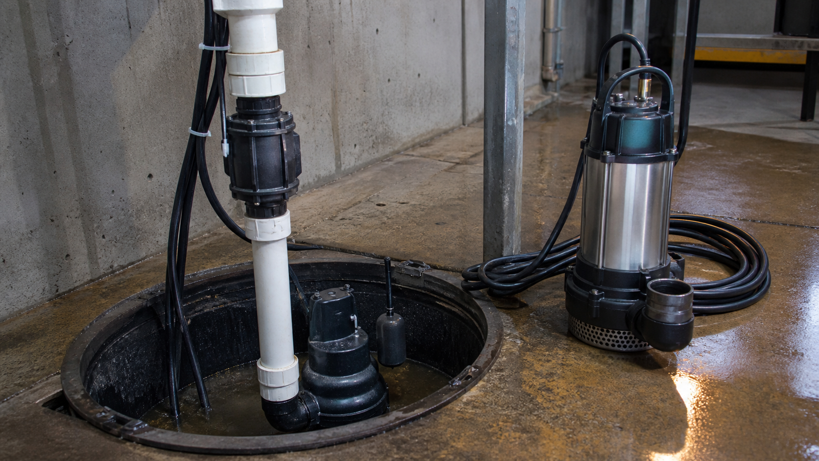
Most sump pumps use submersible construction, which shows that "submersible pump" and "sump pump" describe different attributes. A submersible pump places motor and impeller underwater in a sealed housing; the surrounding liquid cools the motor. A sump pump performs drainage duty—removing groundwater, stormwater, or process water from a collection basin—using either submersible or pedestal motor construction. When comparing these terms, the practical question is whether to install a submersible motor in the pit or mount a pedestal motor above it, both performing the same drainage function. Industrial dewatering pumps, portable construction units, well pumps, and sewage pumps can all use submersible construction while serving entirely different applications. This guide separates motor construction from hydraulic duty, compares installation and maintenance tradeoffs, and shows how to select based on system head, solids profile, cycling pattern, and access constraints.
Key Takeaways
- Submersible describes motor-sealing construction; sump pump describes drainage application—these are not opposing categories.
- Submersible motors depend on liquid cooling and require minimum submergence depth; pedestal motors sit above the liquid and remain accessible for service.
- Sump duty involves cyclic float-controlled operation, low to moderate total head, and occasional small solids depending on inflow source.
- Submersible construction appears in portable dewatering units, sewage grinders, well pumps, and process transfer pumps with different hydraulic profiles.
- Select motor configuration by pit depth, service access, duty cycle, and seal-failure consequences; select pump type by flow, head, solids passage, and liquid chemistry.
- Measure actual submergence, verify NPSHa exceeds the pump’s NPSHr, and confirm float travel before commissioning.
Submersible Describes Construction; Sump Describes Duty
A submersible pump integrates motor and impeller in one housing designed for full immersion. The motor chamber uses mechanical seals or oil-filled barrier sections to exclude water. Liquid surrounding the housing conducts heat from the stator windings; without this convective cooling, the motor overheats rapidly. The power cable enters through a gland or potted connector rated for continuous wet service. This construction appears in well pumps, dewatering equipment, and sewage systems where placing the unit underwater eliminates suction-lift limitations or saves floor space.
A sump pump performs drainage duty: it removes water from a collection basin, typically groundwater seepage, stormwater runoff, or condensate. The basin sits below the discharge point, so the pump lifts water to a drain line or storm sewer. Inflow is intermittent, triggering cyclic on-off operation by float switch. This drainage application does not dictate motor construction. A pedestal sump pump mounts the motor on a column above the pit with only the impeller submerged. A submersible sump pump places the motor-impeller assembly in the pit, requiring deeper basin excavation but offering quieter operation and automatic priming.
Both configurations fulfill the same drainage duty; the difference lies in motor location and cooling method.
How a Submersible Motor Is Sealed and Cooled
Submersible motors use liquid-filled or air-filled chambers isolated from the pumped fluid by mechanical seals. Oil-filled designs use dielectric mineral oil to equalize pressure across seal faces and provide seal lubrication. Air-filled or dry-stator designs employ multiple seals in series; leakage past the innermost seal enters a monitoring chamber before reaching the windings. Both arrangements prevent water contact with electrical components while allowing thermal conduction through the housing wall.
The surrounding liquid removes heat by natural convection. Manufacturers specify minimum submergence depth on the dataplate—this depth must remain above the motor housing during operation. Operating below this level allows the upper housing section to overheat, degrading winding insulation and accelerating seal wear. In shallow sump installations, verify that the float switch "on" setpoint maintains adequate water depth above the motor throughout the pump cycle.
Cable entry represents a common seal failure point. Molded one-piece connectors or epoxy-potted entries provide better moisture resistance than threaded glands with elastomer seals. Inspect cable insulation where it passes through the basin cover; any damage allows water migration along the conductor into the motor housing.
What a Sump Pump System Includes
A sump installation consists of the basin, pump, discharge pipe with check valve, float switch or level sensor, and electrical supply with ground-fault protection. The basin collects inflow from perimeter drains, weep holes, or condensate lines. Basin volume must exceed the pump’s minimum cycle volume to prevent rapid starting; this minimum depends on pump flow rate and acceptable starts per hour.
The discharge pipe connects the pump outlet to the storm sewer or discharge point. A check valve on the discharge line prevents backflow from refilling the basin after pump shutoff. Without this valve, each cycle pumps the same water repeatedly. The valve also prevents reverse rotation during backflow, which can unscrew threaded impellers or damage internal components.
Float switches control operation. A tethered float swings with level rise, actuating a switch at preset heights. Vertical floats slide on a guide rod, triggering reed switches at set levels. Electronic sensors use pressure transducers or ultrasonic distance measurement, offering adjustable setpoints and data-logging capability. Float travel must fit within the basin’s usable depth; in shallow basins, compact floats or pressure switches prevent false trips from contact with the pump housing or basin walls.
Ground-fault circuit interrupter (GFCI) protection is standard for wet-location pumps. A GFCI trips when leakage current exceeds 5 mA, indicating insulation breakdown or seal compromise. Nuisance tripping may result from long cable runs or moisture in junction boxes; isolate the fault source before resetting.
Water, Solids, Head, Cycling, and Float-Control Differences
Parameter | Submersible Sump | Pedestal Sump | Selection Consideration |
|---|---|---|---|
Submergence requirement | Motor must remain submerged during operation | Impeller only submerged | Submersible requires deeper basin |
Solids passage | Model-dependent | Model-dependent | Neither handles trash; effluent applications need larger passages |
Typical head range | Model-dependent | Model-dependent | Both limited by single-stage impeller in standard duty |
Operating noise | Muffled by submergence | Motor cooling fan and bearing noise audible | Consider location relative to occupied spaces |
Service access | Full removal from pit required | Motor accessible without pit entry | Affects maintenance time and cost |
Seal failure consequence | Water enters motor, shorts windings, trips GFCI | No immersion seals | Submersible failure stops pumping immediately |
Minimum pit depth | Must accommodate motor plus submergence margin | Accepts shallower excavation | Site excavation depth may constrain choice |
Both submersible and pedestal sump pumps handle clean to lightly contaminated water—foundation drainage, stormwater, or condensate. Neither design accommodates sewage, grease, or trash-laden streams. Solids passage specification indicates the largest spherical particle that can transit the impeller without obstruction; exceeding this diameter causes clogging. Inflow containing larger debris requires inlet screening or a pump with vortex or semi-open impeller geometry.
Head requirements equal vertical lift from pit bottom to discharge point plus piping friction loss. Measure static lift and estimate friction loss; confirm the operating point against the manufacturer’s pump curve at expected flow rate.
Cycling frequency affects motor thermal stress and mechanical wear. Frequent starts increase winding temperature swing and impose shock loads on couplings. If the pump starts more than the manufacturer’s recommended cycle rate, increase basin volume or adjust float differential. Undersized basins cause short-cycling; oversized basins allow extended water retention, which may create odor in wastewater applications.
Portable, Dewatering, Sewage, Well, and Sump Variants
Submersible construction extends beyond sump applications. Portable dewatering pumps for construction sites use sealed motors but prioritize high flow at low head to empty excavations or flooded areas quickly. These units include bottom suction screens and handle larger solids because site water contains sand and gravel. Operation is continuous during active dewatering, unlike cyclic sump duty.
Well pumps are submersible multistage centrifugal designs optimized for narrow, deep installations. The motor sits below the impeller stack, and the cable attaches to the drop pipe. Well pumps require constant submergence and clean water; abrasive particles erode wear rings and bearings, reducing efficiency and potentially seizing the rotor.
Sewage and effluent pumps use submersible motor construction but feature larger solids passages and semi-open or vortex impellers that resist fibrous material entrapment. Grinder pumps add a cutter assembly ahead of the impeller, reducing solids to pumpable size before entry. Both types install in sewage basins or lift stations rather than sump pits, handling organic waste and typically higher discharge pressures to reach municipal collection systems.
Each variant employs the same motor-sealing technology but differs in impeller design, materials selection, and control requirements. Installing a sump pump in sewage service invites clogging; using a sewage pump for clean water adds unnecessary cost and reduces efficiency at typical sump head ranges.
Installation, Service Access, and Failure Consequences
Submersible sump pumps require basin depth sufficient to maintain minimum submergence after the float switches the pump off. Check the manufacturer’s dataplate for required submergence depth and ensure the basin provides this depth plus float differential plus margin for sediment accumulation. Shallow basins require pedestal configuration or external float mounting higher on the basin wall.
Discharge piping must slope upward continuously with no high points where air can accumulate. Air pockets reduce flow and may cause cavitation or prime loss. Install the check valve in a vertical section near the pump discharge inside the basin; leakage then drains into the pit rather than back into the pump casing.
Service access on submersibles requires lifting the complete motor-impeller assembly from the pit. If the pit has a cover or sits in confined space, arrange lifting clearance and ventilation before installation. Pedestal pumps allow motor and bearing inspection without impeller removal, but the submerged impeller and shaft are more exposed to debris damage.
Seal failure in a submersible motor floods the motor cavity, shorts the windings, and trips the GFCI. Pumping stops until motor replacement or rebuild. Pedestal motors avoid immersion but experience higher humidity exposure, which degrades insulation over time. Both configurations benefit from annual inspection: verify cable insulation integrity, measure winding insulation resistance to ground, test float operation, and confirm check-valve seating.
Power failure causes most sump system failures. Battery backup systems or dual pumps with separate circuits provide redundancy. Without backup, the basin overflows during outages, so size the basin to hold peak inflow for the expected outage duration if unattended operation is required.
Choose by Liquid and System, Not the Label Alone
Selecting between submersible and pedestal motor construction depends on pit geometry, maintenance access requirements, and noise tolerance. Shallow excavations favor pedestal designs; deep basins favor submersibles. Occupied mechanical rooms favor submersibles for noise reduction; remote outdoor installations favor pedestals for accessible maintenance. Both constructions perform identical sump duty if the pump curve matches the system curve at the operating point.
Selecting the correct pump type—sump, sewage, effluent, well, or dewatering—depends on liquid properties and solids content. Clean groundwater or stormwater in residential or commercial basins requires sump pumps. Domestic wastewater requires sewage pumps or grinder pumps. Construction site water with abrasive particles requires dewatering pumps with wear-resistant materials. Deep groundwater supply requires multistage well pumps.
Match the pump curve to the system curve at the required flow rate. Consult the manufacturer’s certified performance curve and identify the head at your target flow. Operating far from best efficiency point (BEP) increases vibration, power consumption, and seal wear. If the duty point falls on the steep or flat curve regions, reconsider pipe sizing or impeller selection.
Verify net positive suction head available (NPSHa) exceeds the pump’s required NPSHr. For a sump pump, NPSHa equals atmospheric pressure head plus static submergence depth, minus vapor pressure head and suction-side friction losses. The manufacturer’s installation manual provides NPSHr; compare it against your calculated NPSHa to confirm adequate margin. For deeper wells or elevated liquid temperatures, calculate NPSHa from site-specific conditions and fluid properties.
Commission every installation by measuring pump-on and pump-off levels, verifying float travel clearance, checking valve seating, and confirming discharge flow. Record baseline motor current and compare against nameplate rating; elevated current indicates obstruction or overpressure, while low current suggests reduced flow or impeller damage.
FAQs
Can a sewage pump substitute for an undersized sump pump?
A sewage pump will move clean water but introduces unnecessary cost and reduced efficiency. Sewage pumps use vortex or semi-open impellers optimized for large solids passage, not head generation. At typical sump head ranges, these impellers deliver lower head per stage than closed sump-pump impellers, potentially requiring higher motor power to reach the same discharge elevation. If sump duty exceeds standard residential capacity, select an industrial sump or dewatering pump rated for the required flow and head rather than oversizing a sewage unit.
What occurs when a submersible pump operates below minimum submergence?
The motor overheats because insufficient liquid surrounds the housing to remove generated heat. Winding insulation degrades, and internal temperature rise can short windings to ground, tripping the GFCI or circuit breaker. Brief exposure may not cause immediate damage, but repeated low-level operation destroys the motor. Adjust the float switch to maintain the manufacturer’s specified minimum depth during pump operation.
Why does a sump pump run briefly then stop repeatedly?
Short-cycling typically indicates check-valve leakage; the discharge pipe drains back into the pit after each stop, re-triggering the float. Inspect the check valve for debris on the seat or worn sealing surfaces. Alternatively, short-cycling may result from undersized basin volume where the pump evacuates usable storage faster than the float can respond. Increase float differential or add basin capacity.
Can a pedestal sump pump draw from deeper depth than a submersible?
No. Both are centrifugal pumps subject to the same NPSHa limitations. A pedestal’s impeller sits at the shaft bottom inside the pit—only the motor is above water. Centrifugal pumps generally cannot lift water more than atmospheric pressure limits allow, and most sump pumps assume positive submergence rather than suction lift. For deeper pits, use a submersible model rated for the depth or install the pump at a lower elevation.
How do I detect submersible motor seal failure?
Measure insulation resistance between motor leads and ground using a megohmmeter; readings below 1 MΩ indicate moisture penetration. GFCI trips during operation strongly suggest seal compromise. Some submersibles include moisture sensors or leak-detection probes in the oil chamber; consult the manual for sensor terminal identification. After seal failure, disassemble the motor, dry all components, replace seals, and rewind if windings are compromised before returning to service.
Conclusion
Submersible pump and sump pump describe different attributes—motor construction versus drainage application—and are not opposing selections. Most sump pumps use submersible construction, but submersible motors also serve well, sewage, and dewatering duties with distinct hydraulic and solids requirements. Choose motor configuration—submersible or pedestal—based on available pit depth, maintenance access, and acceptable noise levels. Choose pump type—sump, sewage, effluent, or dewatering—based on liquid chemistry, solids size, and system head. Validate your selection by plotting the system curve against the manufacturer’s certified pump curve, confirming the duty point falls near BEP and that NPSHa exceeds NPSHr by adequate margin. Before commissioning, measure and record float actuation levels, verify check-valve operation, and document baseline motor current for comparison during future maintenance inspections.