
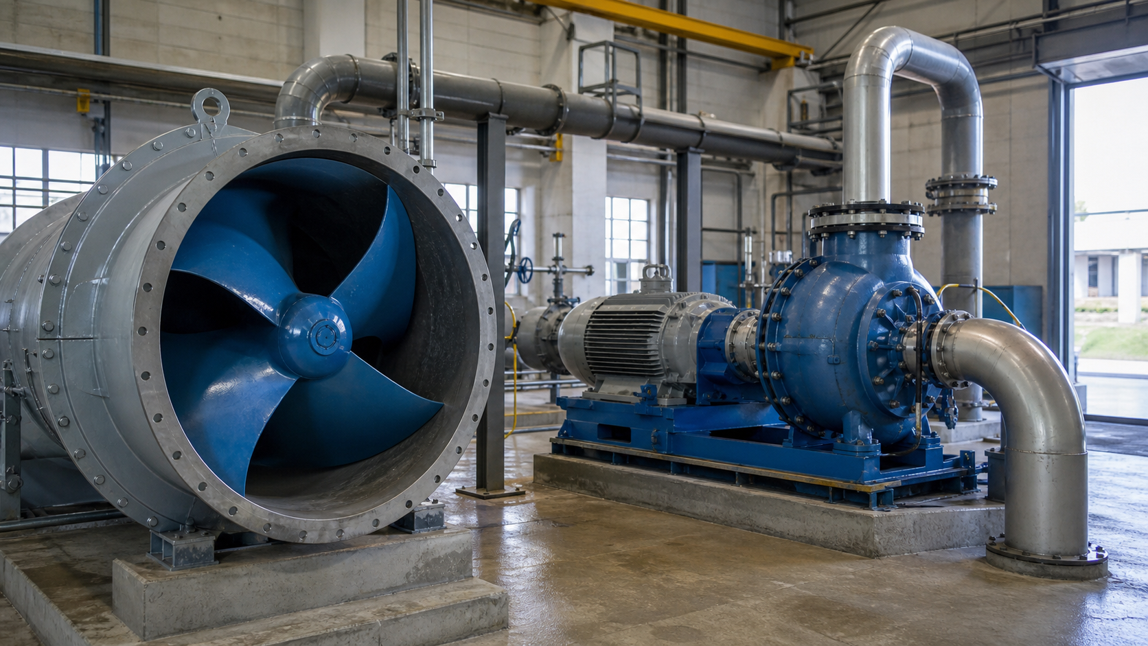
An axial flow pump accelerates liquid parallel to the shaft axis, while a centrifugal pump throws liquid radially outward. This difference in flow direction creates distinct performance shapes: axial pumps deliver high flow at low head, centrifugal pumps cover a broader head range. Select axial flow when your system curve shows high capacity with total dynamic head typically under 30 feet—flood control, cooling tower circulation, or raw water intake. Choose centrifugal when your duty point requires moderate to high head—booster service, process transfer, or well pumping. Match the pump’s published curve to your calculated system curve, placing the operating point within the manufacturer’s recommended range to avoid runout or shutoff damage.
Key Takeaways
- Axial flow pumps move liquid parallel to the shaft and deliver high flow at low head; centrifugal pumps redirect flow radially and cover wider head ranges.
- Specific speed separates the families: axial flow designs operate above 9,000 (US units), most centrifugal designs fall between 500 and 4,000.
- Axial flow pumps require continuous submergence or flooded suction and produce steep head-capacity curves; centrifugal pumps tolerate varied suction conditions and provide flatter operating envelopes.
- Power curves differ: axial flow pumps show rising power with flow, centrifugal pumps with backward-curved vanes peak near best efficiency point.
- Selection depends on your measured system curve and duty point, not on general application categories alone.
Axial and Radial Flow Describe Different Energy Transfer
Both types spin an impeller to add energy to liquid, but the flow path differs. In an axial flow pump, liquid enters along the shaft centerline and exits parallel to the shaft after passing through propeller-like blades. The impeller imparts velocity in the axial direction; fixed guide vanes downstream convert velocity head to pressure head. Pressure rise is modest because the flow path remains straight and centrifugal acceleration is minimal.
In a centrifugal pump, liquid enters at the impeller eye near the shaft, accelerates radially outward through curved vanes, and exits into a volute or diffuser. The impeller converts shaft torque into kinetic energy, and the volute or diffuser converts velocity head to static pressure. The radial throw produces centrifugal acceleration proportional to the square of rotational speed and impeller diameter, enabling higher single-stage heads than axial designs.
The head-capacity curve reveals the difference. An axial flow pump’s curve is steep; closing the discharge valve increases head only slightly before the motor overloads. A centrifugal pump’s curve is flatter, with shutoff head often reaching multiples of the head at best efficiency point. This controls how each pump responds to throttling, system resistance changes, and parallel operation.
Impeller Geometry and Flow Direction
Axial flow impellers resemble marine propellers with three to six blades. The blades twist along their length to maintain the correct angle of attack from hub to tip. Liquid flows through the impeller annulus without changing radial position. Guide vanes downstream straighten the flow and recover velocity head.
Centrifugal impellers use enclosed, semi-open, or open vane configurations. Enclosed impellers have shrouds on both sides and require close clearance to wear rings. Semi-open impellers omit the front shroud and rely on close clearance between vane tips and casing. Open impellers have no shrouds and handle solids or abrasives with reduced efficiency. The vane exit angle and width determine head and flow at the duty point. A backward-curved vane produces a rising power curve and stable operation.
Flow direction determines mounting options. Axial flow pumps typically use vertical configurations with bottom suction and top discharge, or horizontal inline arrangements. Centrifugal pumps offer end suction, inline, split-case, submersible, or vertical turbine mounting. Installation space, piping layout, and available NPSH constrain the choice.
Flow, Head, Specific Speed, and Curve Shape
Specific speed quantifies the hydraulic design and separates pump families. In US units:
N<sub>s</sub> = N × √Q / H<sup>0.75</sup>
where:
- N = rotational speed, rpm
- Q = flow at best efficiency point, gpm
- H = head per stage at BEP, feet
Axial flow pumps operate at specific speeds above 9,000. Mixed-flow pumps span 4,000 to 9,000. Centrifugal pumps range from 500 to 4,000, with low specific-speed designs producing high head at low flow.
Specific speed sets curve shape. A low specific-speed centrifugal pump has a flat curve; head drops gradually as flow increases. A high specific-speed axial flow pump has a steep curve; head drops sharply with flow, and shutoff head may rise only moderately above BEP head. The steep curve means small changes in system resistance cause large flow swings, and throttling offers limited head control.
Example (hypothetical calculation): A 1,200 rpm axial flow pump delivers 20,000 gpm at 15 feet head. Specific speed is 1,200 × √20,000 / 15<sup>0.75</sup> = 1,200 × 141.4 / 8.71 = 19,500, confirming axial flow design. A 1,750 rpm centrifugal pump delivers 1,000 gpm at 150 feet per stage. Specific speed is 1,750 × √1,000 / 150<sup>0.75</sup> = 1,750 × 31.6 / 40.9 = 1,350, confirming conventional centrifugal geometry.
Power curves differ by design. Axial flow pumps show rising power with flow; power at maximum flow can exceed nameplate motor rating. Centrifugal pumps with backward-curved vanes have non-overloading power curves; power peaks near BEP and drops at higher flow. Verify that motor horsepower exceeds required power across the expected operating range, not just at the design point.
Intake, Submergence, Cavitation, and Operating Range
Axial flow pumps require adequate submergence to prevent surface vortices and air entrainment. Manufacturer data and intake modeling determine the actual requirement for specific installations. Vertical axial flow pumps in wet wells, cooling tower basins, or river intakes must maintain submergence under all operating conditions, including drawdown.
Net positive suction head required (NPSHr) for axial flow pumps increases sharply with flow because propeller tip speed and blade loading rise. NPSHa at the suction flange must exceed NPSHr by the manufacturer’s recommended margin to avoid cavitation.
Centrifugal pumps typically show lower NPSHr at equivalent flows because the radial impeller operates at lower blade velocities near the eye. Double-suction impellers halve the inlet velocity and further reduce NPSHr. Calculate NPSHa using:
NPSHa = h<sub>atm</sub> + h<sub>s</sub> – h<sub>vp</sub> – h<sub>f,suction</sub>
where:
- h<sub>atm</sub> = atmospheric pressure head, feet
- h<sub>s</sub> = static suction head (positive if flooded, negative if lift), feet
- h<sub>vp</sub> = vapor pressure head at pumping temperature, feet
- h<sub>f,suction</sub> = friction and minor losses in suction piping, feet
Operating range differs between types. Axial flow pumps deliver stable performance within a narrower band around BEP. Operating below minimum continuous flow causes recirculation at blade tips and hub, leading to vibration, noise, and mechanical damage. Operating beyond maximum flow risks motor overload. Centrifugal pumps tolerate a broader range, with many designs stable across wider flow variations for continuous operation. Consult the manufacturer’s certified curve for specific limits.
Solids handling varies by impeller type. Axial flow pumps pass large solids—the passage diameter approaches the impeller eye diameter—making them suitable for raw water with debris. Centrifugal pumps handle solids based on impeller design: enclosed impellers pass smaller solids, open or recessed impellers accommodate larger debris. Consult manufacturer data for specific solids-passage dimensions.
Footprint, Driver, Control, and Maintenance
Axial flow pumps occupy larger footprints than equivalent-capacity centrifugal pumps because the impeller diameter approaches the discharge pipe diameter. A vertical axial flow installation requires a deep intake structure and tall motor-column assembly. Centrifugal pumps, especially horizontal split-case or inline designs, fit within smaller equipment rooms.
Motor selection depends on the power curve. Axial flow pumps with rising power curves require motors sized for maximum expected flow, not just the duty point. For variable-speed operation, install a VFD rated for full motor horsepower and program a flow or power limit to prevent overload. Centrifugal pumps with non-overloading curves can use motors sized closer to BEP power with a service factor.
Variable frequency drives change performance according to affinity laws: flow varies with speed, head varies with speed squared, power varies with speed cubed. Reducing speed on an axial flow pump moves the operating point along the system curve, but the steep pump curve requires large speed changes for moderate flow adjustments. Reducing speed on a centrifugal pump offers finer flow control and energy savings when the system curve is friction-dominated.
Maintenance intervals depend on operating environment and duty cycle. Axial flow pump bearings and seals in submerged or humid service require oil-lubricated or water-lubricated designs with regular inspection. Impeller blade tips erode in abrasive service. Centrifugal pump wear rings, mechanical seals, and bearings follow manufacturer-recommended intervals—actual life depends on liquid properties, operating point stability, and alignment quality.
Seal systems differ by installation. Vertical axial flow pumps use line-shaft bearings and a top-mounted packing box or mechanical seal. Horizontal and centrifugal designs use component or cartridge mechanical seals. For hazardous or high-temperature liquids, specify appropriate seal flush, quench, and barrier systems following API 682 or manufacturer guidance.
Flood Control, Cooling Water, Process, and Transfer Applications
Axial flow pumps suit flood control and drainage where large volumes move against low static lift. Storm water lift stations, levee pumps, and river diversions may require flows above 10,000 gpm with total heads under 30 feet. The high capacity and solids passage make axial flow practical where centrifugal designs would require impractical sizes. Install trash racks and bar screens upstream to protect the impeller.
Cooling water circulation for power plants, refineries, and HVAC systems often uses axial or mixed-flow pumps when the cooling tower basin provides low available head and flow exceeds several thousand gpm. The steep curve requires careful system design; balance parallel flows using throttle valves or VFDs. Centrifugal pumps serve smaller systems or installations with long piping runs and high friction losses.
Process and chemical transfer applications favor centrifugal pumps. Booster stages, reactor feed, and product transfer require controlled head, stable operation across varying flows, and compatibility with seal systems and materials. Horizontal end-suction, inline, or ANSI process pumps handle moderate flows and heads from tens to hundreds of feet. For corrosive or high-temperature service, specify alloy construction and appropriate seal plans.
Raw water intake and irrigation span both families. Low-lift irrigation delivering several thousand gpm against modest head uses axial or mixed-flow designs. High-lift irrigation or intakes serving treatment plants use multistage centrifugal pumps. Calculate the system curve including static lift, piping friction, and seasonal demand variation, then select the pump that places the duty point near BEP.
Selection Table by System Requirement
System Requirement | Typical Flow (gpm) | Typical Head (ft) | Common Type | Key Considerations |
|---|---|---|---|---|
Flood control, storm water | 10,000 – 100,000+ | 5 – 30 | Axial flow | Submergence, trash screens, motor overload protection |
Cooling tower circulation | 5,000 – 80,000 | 10 – 25 | Axial or mixed-flow | Parallel operation, VFD for load variation, basin depth |
Low-lift irrigation | 5,000 – 50,000 | 10 – 40 | Axial or mixed-flow | Intake design, water level variation, debris passage |
High-lift irrigation, water supply | 500 – 10,000 | 50 – 300 | Multistage centrifugal | NPSHa, column sizing, well depth |
Process transfer, booster | 50 – 5,000 | 50 – 400 | Horizontal centrifugal | Seal plan, material compatibility, turndown range |
Sewage, wastewater | 100 – 10,000 | 15 – 100 | Centrifugal (non-clog) | Solids content, fiber handling, wet well design |
Slurry, abrasive service | 100 – 5,000 | 30 – 150 | Centrifugal (open impeller) | Wear rate, material hardness, flush systems |
This table provides initial guidance; final selection requires plotting the system curve, reviewing manufacturer curves, and confirming that the duty point falls within the pump’s efficient operating range. Understanding the performance differences between pump types prevents operating-point mismatch.
FAQs
Can I use a centrifugal pump for flood control applications?
Yes, if the required flow and head match a centrifugal pump’s efficient range. Centrifugal pumps become less practical above certain flow rates at low head because impeller diameter, motor size, and cost escalate. If your system requires tens of thousands of gpm at low head, an axial flow pump typically offers lower capital cost and better solids passage. If the system curve includes significant piping friction and head exceeds 40 feet, a centrifugal pump may be appropriate. Plot the system curve and compare it to manufacturer performance data.
What happens if I operate an axial flow pump below minimum continuous flow?
Operating below the manufacturer’s minimum continuous flow triggers recirculation at blade tips and hub. Recirculation creates turbulent eddies that erode the impeller and guide vanes, increase vibration, and reduce efficiency. The pump may lose prime or develop cavitation even when NPSHa exceeds NPSHr. If your system requires turndown below this threshold, install a VFD to reduce speed, add a recirculation line to maintain minimum flow, or run multiple smaller pumps in parallel during low-demand periods.
How do I calculate the system curve for pump selection?
Calculate total dynamic head at multiple flow rates. TDH equals static lift plus friction losses in suction and discharge piping, fittings, valves, and downstream equipment. Use the Darcy-Weisbach or Hazen-Williams equation for friction loss. Include minor losses for elbows, tees, reducers, and trash racks. Plot TDH versus flow on the same chart as the pump curve. The intersection is the operating point. Selection methods that consider the full system ensure the operating point falls within the pump’s efficient range and that NPSHa exceeds NPSHr across the operating envelope.
Do axial flow pumps require more maintenance than centrifugal pumps?
Maintenance frequency depends on operating environment and duty cycle, not pump type alone. Axial flow pumps submerged in raw water or storm water require frequent bearing, seal, and impeller inspection because debris, silt, and biological growth accelerate wear. Line-shaft bearings need periodic lubrication and alignment. Centrifugal pumps in clean process service may run longer between seal and bearing replacements. Centrifugal sewage pumps handling solids or abrasives require impeller and wear ring inspection at shorter intervals. Follow the manufacturer’s maintenance schedule and adjust based on vibration monitoring, bearing temperature, and seal leakage trends.
Can I retrofit a centrifugal pump with an axial flow impeller?
No. The casing, volute, and shaft design are specific to the hydraulic geometry. A centrifugal casing collects flow radially and converts velocity to pressure in an expanding volute. An axial flow pump requires a tubular casing with guide vanes and a straight discharge. The shaft diameter, bearing spacing, and seal arrangement also differ. If your application requirements have shifted toward high flow and low head, replace the entire pump assembly. Conduct a new system analysis, select a pump that matches the revised duty point, and verify that the intake structure provides adequate submergence and approach velocity.
Conclusion
Choose an axial flow pump when your system curve demands high flow at low head and when solids passage and submergence conditions are acceptable. Choose a centrifugal pump for moderate to high head applications, broader operating ranges, and installations where space or suction conditions constrain the design. Plot your system curve, compare it to manufacturer performance curves, and verify that the duty point falls within the recommended operating range before finalizing the selection. Obtain certified curves, motor data, and NPSH curves from your supplier, and confirm submergence, seal plan, and material compatibility during specification review.