
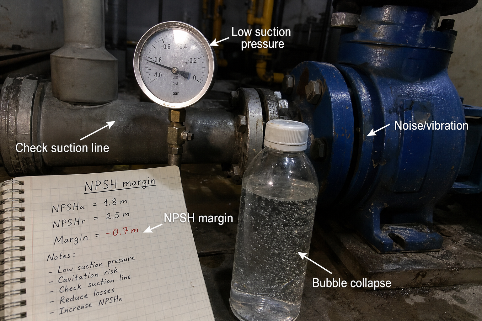
Field-style article image prepared for centrifugal pump cavitation.
Cavitation in centrifugal pumps occurs when local static pressure at the impeller inlet falls below the vapor pressure of the pumped fluid, causing vapor bubbles to form and then violently collapse as they move into higher-pressure regions. The collapse generates shock waves that erode impeller and casing surfaces, reduce pump performance, and produce characteristic noise and vibration.
When specifying a replacement pump for a condensate return system, the maintenance engineer discovers pitting damage on the impeller eye and hears gravel-like noise during operation. Discharge pressure fluctuates even though suction pressure appears stable. These symptoms point to cavitation, which requires both immediate correction and a margin review to prevent recurrence.
The decision to accept or reject a pump for a given installation depends on comparing available NPSH (NPSHa) against required NPSH (NPSHr) with an adequate safety margin, typically 0.5 to 1.0 meters for most industrial services.
Key Takeaways
- Cavitation damage results from vapor bubble collapse, not bubble formation alone; the collapse location determines where erosion appears.
- NPSHa must exceed NPSHr by a margin that accounts for system uncertainties, fluid temperature variation, and wear-related performance degradation.
- Symptoms include noise, vibration, head loss, flow reduction, and physical damage concentrated near the impeller eye and inlet vane surfaces.
- Prevention requires validating suction conditions, controlling fluid temperature, reducing suction line losses, and confirming pump operation within the allowable range on the performance curve.
Cavitation Mechanism and Damage Pattern
Vapor bubbles form when liquid enters the impeller eye and accelerates, causing local pressure to drop below vapor pressure. The bubbles travel with the flow into zones of increasing pressure created by the impeller rotation.
When pressure rises above vapor pressure, bubbles collapse inward at high velocity. The collapse produces micro-jets and shock waves that impact nearby metal surfaces. Repeated collapse events remove material through fatigue and erosion, creating the characteristic pitted surface texture on impeller vanes and shrouds.
Damage concentrates at the impeller eye because that is where bubbles first enter the higher-pressure zone. Severe cavitation extends to the vane leading edges and suction-side surfaces.
Recognizing Cavitation Symptoms
Operators and engineers identify cavitation through a combination of audible, measurable, and visual indicators.
**Noise and vibration**: The pump produces sounds similar to gravel or marbles passing through the casing. Vibration amplitude increases at blade-pass frequency and its harmonics. These signatures distinguish cavitation from mechanical imbalance or misalignment.
**Performance degradation**: Head and flow drop below curve values even when speed and impeller diameter remain unchanged. Discharge pressure fluctuates when suction conditions are marginal. Efficiency declines as vapor occupies volume that should contain liquid.
**Physical evidence**: Inspection reveals pitting, sponge-like surfaces, or material removal on impeller inlet areas. Paint or coatings near the suction flange show erosion patterns. Shaft seals fail prematurely due to vibration and axial thrust changes.
NPSH Margin Calculation
Net Positive Suction Head Available (NPSHa) quantifies the pressure margin at the pump inlet above vapor pressure. The system designer calculates NPSHa using:
**NPSHa = (P_atm + P_static – P_vapor – h_loss) / (ρ × g)**
Where:
- P_atm = atmospheric pressure at site elevation (Pa)
- P_static = static pressure from liquid level or upstream pressure (Pa)
- P_vapor = vapor pressure of fluid at pumping temperature (Pa)
- h_loss = friction and fitting losses in suction piping (m)
- ρ = fluid density (kg/m³)
- g = gravitational acceleration (9.81 m/s²)
The pump manufacturer provides NPSHr from testing, shown on the performance curve. NPSHr increases with flow rate because higher flows mean higher inlet velocities and greater local pressure drops.
**Design margin**: Specify NPSHa ≥ NPSHr + 0.5 m for clean, cold water services. Increase the margin to 1.0 m or more for hot water, hydrocarbons, or fluids near their boiling point. Account for worst-case conditions: lowest liquid level, highest temperature, maximum expected flow.
Prevention Checks for Installation and Operation
**Suction piping layout**: Minimize elbow count and pipe length between the source and pump inlet. Use eccentric reducers (flat side up) rather than concentric reducers to avoid air pockets. Maintain straight-run requirements upstream of the pump per manufacturer specifications, typically 5 to 10 pipe diameters.
**Suction pressure boost**: Elevate the supply tank to increase static head. Pressurize closed suction vessels when atmospheric sources are impractical. Install a suction stabilizer or pulsation dampener if the system creates pressure waves.
**Temperature control**: Lower fluid temperature to reduce vapor pressure. Insulate hot suction lines to prevent heat gain from surroundings. Monitor fluid temperature at the pump inlet, not just at the source, because friction heating occurs in long piping runs.
**Operating range**: Confirm the operating point stays within the manufacturer’s preferred range, typically between 70% and 120% of best efficiency point (BEP) flow. Cavitation risk increases at high flows where NPSHr rises sharply. Throttle discharge valves rather than suction valves to control flow.
Suction Condition Scenarios
Different system configurations create distinct NPSHa profiles that require tailored prevention strategies.
**Flooded suction (tank above pump)**: NPSHa depends on static head from liquid level. Level variations directly change available margin. Install level monitoring and low-level interlocks to prevent vortex formation and air entrainment as level drops.
**Suction lift (pump above source)**: NPSHa starts low because atmospheric pressure must push liquid up to the pump. Altitude reduces P_atm, cutting into the available margin. Use a foot valve to maintain prime and minimize suction line losses through oversized piping.
**Inline booster (positive suction pressure)**: Upstream pressure supplements atmospheric pressure, providing higher NPSHa. Confirm that upstream equipment maintains pressure during transient conditions such as startup or valve operations. Pressure drops during these events can trigger sudden cavitation.
FAQs
Can cavitation occur even when NPSHa exceeds NPSHr by the recommended margin?
Yes, if the pump operates far from its design point or if internal recirculation develops at low flows. Some pump designs exhibit suction recirculation below 60% of BEP flow, creating local low-pressure zones that initiate cavitation despite adequate inlet conditions. The manufacturer’s minimum continuous flow rating accounts for this risk.
How does fluid viscosity affect cavitation risk?
Higher viscosity increases friction losses in suction piping, reducing NPSHa. Viscosity also changes the pump’s performance curve and NPSHr, typically increasing required NPSH at a given flow. Use viscosity-corrected curves from the manufacturer and recalculate suction losses with actual fluid properties rather than water equivalents.
What is the difference between cavitation and flashing?
Cavitation involves bubble formation and collapse within the pump because pressure recovers above vapor pressure. Flashing occurs when fluid pressure stays below vapor pressure through the pump and into the discharge line, so vapor does not collapse. Flashing requires a different solution approach focused on downstream pressure control or fluid cooling before the pump.
Should I oversize the pump to reduce cavitation risk?
No. Oversizing moves the operating point left on the curve toward lower flows where efficiency drops and suction recirculation risk increases. Instead, select a pump with BEP near the required duty and confirm NPSHr at that flow is well below available NPSH. Consider a larger impeller diameter in the same casing to reach the required head without oversizing the hydraulic frame.
Conclusion
Preventing cavitation in centrifugal pumps requires validating that NPSHa exceeds NPSHr by a margin sufficient to cover system uncertainties and transient conditions. During commissioning, measure suction pressure, fluid temperature, and flow rate to confirm the installed system delivers the predicted NPSHa. Monitor noise and vibration for early detection, and inspect impellers during scheduled maintenance to catch erosion before it progresses to complete vane failure.