
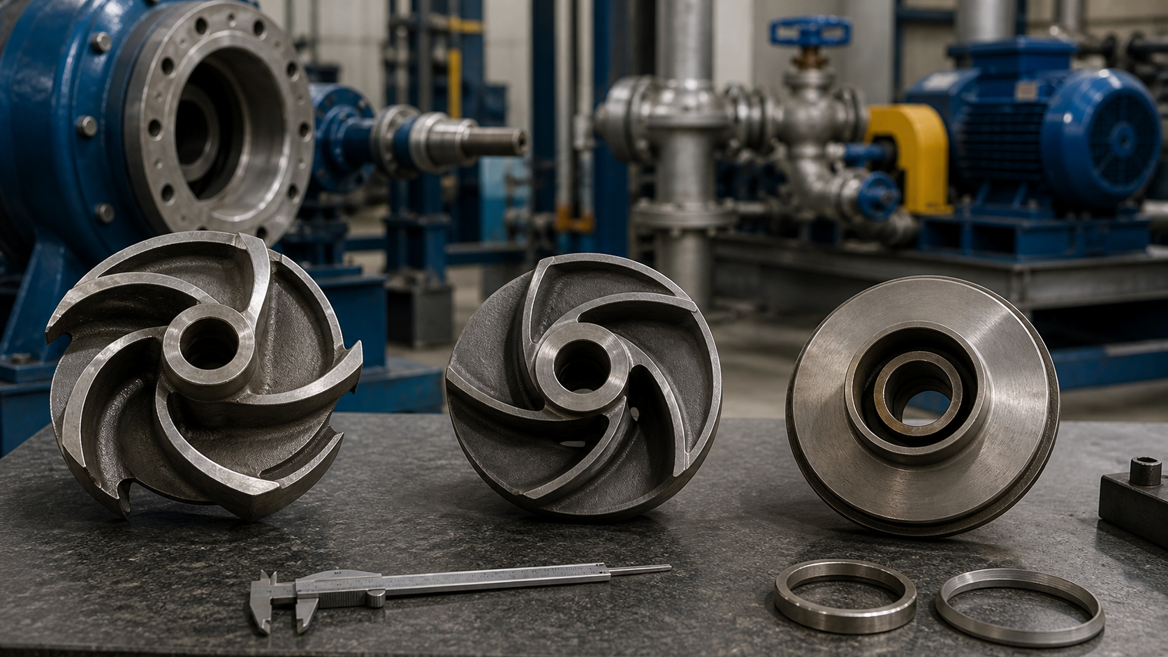
Place three impellers of identical diameter and vane count on a workbench. One has front and rear shrouds fully enclosing the vane channels. The second has a rear shroud only, leaving the vanes open on one side. The third has no shrouds at all, exposing the vanes from both sides. Each moves the same rated flow at the same speed, but the shroud configuration changes the clearance interface, the ability to handle solids, the efficiency envelope, and the maintenance procedure.
Closed impellers deliver the highest efficiency in clean liquids because the shrouds confine the flow and reduce recirculation. Semi-open impellers sacrifice some efficiency for adjustable clearance and better solids passage. Open impellers handle stringy or abrasive solids with minimal clogging but operate at lower efficiency and require more frequent wear inspection. Selection depends on the fluid properties, the acceptable efficiency penalty, the installed clearance control, and the maintenance resources available at the site.
Key Takeaways
- Closed impellers use front and rear shrouds to confine flow, delivering peak efficiency but requiring wear-ring replacement when axial clearance grows beyond specification.
- Semi-open impellers mount a single rear shroud and rely on adjustable front clearance between the vanes and casing, offering a compromise between efficiency and solids passage.
- Open impellers expose vanes on both sides, maximizing solids and fibrous-material handling at the cost of lower efficiency and increased recirculation losses.
- All three types can share the same radial, mixed-flow, or axial vane geometry; shroud configuration and vane angle are independent design choices.
- Selection requires matching the system curve, fluid properties, solids loading, and maintenance capability to the impeller’s efficiency envelope and wear characteristics.
- Inspect front and rear clearances at commissioning and during rebuilds; clearance growth degrades head and efficiency in semi-open and open designs.
The Shroud Defines the Basic Impeller Type
A shroud is a flat or contoured disk that covers the impeller vanes on the suction side (front shroud) or the hub side (rear shroud). The shroud creates a boundary for the flow passage between adjacent vanes, preventing liquid from leaking across the vane tip and recirculating back to the low-pressure zone. When both shrouds are present, the vane channel becomes a closed passage with fixed geometry. When one or both shrouds are removed, the vane tip is exposed and a running clearance must be maintained between the tip and the stationary casing or wear plate.
The closed, semi-open, and open classifications describe this shroud arrangement:
- Closed impeller: Front and rear shrouds fully enclose the vanes. The rotating shrouds run against stationary wear rings, and axial clearance is controlled by the wear-ring gap.
- Semi-open impeller: Rear shroud only. The vane tips face the front casing or cover plate, and clearance is adjusted by moving the impeller axially or by shimming the casing.
- Open impeller: No shrouds. Both vane surfaces are exposed, and clearance must be maintained on both the suction and discharge sides.
The choice of shroud configuration directly affects efficiency, solids tolerance, wear-rate sensitivity, and field adjustment procedures. Clearance is the single most important field-adjustable parameter for semi-open and open impellers. Manufacturers specify a nominal running clearance and provide clearance-versus-performance curves in the instruction manual. Exceeding the maximum clearance reduces head and increases power draw due to recirculation.
Closed Impellers: Controlled Passages and Wear Interfaces
Closed impellers confine the flow between two shrouds, creating a well-defined passage from eye to discharge. The liquid enters axially through the eye, accelerates as it moves radially outward between the vanes, and exits tangentially into the volute or diffuser. Because the shrouds prevent flow from escaping across the vane tips, the impeller can maintain the design velocity profile and deliver the highest efficiency in its class.
The rotating shrouds run against stationary wear rings mounted in the casing. The wear-ring clearance controls the leakage from the discharge zone back to the suction. As the wear rings erode or corrode, the clearance opens and internal recirculation increases. When the clearance exceeds the manufacturer’s limit, the pump loses head and efficiency even though the impeller vanes remain intact.
Closed impellers are the standard choice for clean water, cooling water, boiler feed, condensate, and other services where the liquid contains minimal suspended solids and the system operates near the design duty point most of the time. The narrow passages between shrouds make closed impellers unsuitable for liquids with fibrous material, rags, or solids larger than a few millimeters. A closed impeller centrifugal pump in a wastewater lift station will clog unless the incoming flow is screened to remove debris.
Maintenance requires disassembling the pump to inspect and replace the wear rings. The shrouds themselves rarely wear unless the liquid is abrasive, but the wear rings must be renewed when clearance exceeds specification. Replacing wear rings requires removing the impeller, pressing or machining out the old rings, installing new rings, and reassembling the pump with proper alignment. In high-availability services, operators may keep a complete spare impeller and wear-ring set on site to minimize downtime.
Semi-Open Impellers: One Shroud and Adjustable Clearance
A semi-open impeller retains the rear shroud for structural support and axial confinement but leaves the vane tips exposed on the suction side. The vanes face a stationary casing cover or front plate, and the clearance between the vane tip and the plate determines the recirculation loss. Unlike a closed impeller, this clearance can be adjusted in the field by repositioning the impeller axially or by adding or removing shims behind the casing cover.
The adjustable clearance offers two advantages: it allows the operator to compensate for wear without a full rebuild, and it provides a wider passage on the suction side that can accommodate small solids and fibrous material. The rear shroud still confines the flow on the hub side, so the impeller retains reasonable efficiency while handling solids that would jam a closed design.
Semi-open impellers are common in process water, light slurry, and municipal wastewater pumps where the liquid contains grit, sand, or small debris but remains pumpable without a grinder. The vane tips and the facing plate both wear over time, gradually opening the clearance. When performance drops below the acceptable range, the operator can adjust the clearance by loosening the bearing housing, shifting the rotor assembly forward, and retightening. Some designs use threaded adjusters or shim packs to control the axial position without disturbing the mechanical seal.
Clearance adjustment is a balance. Too little clearance risks rubbing contact between the rotating vane tips and the stationary plate, generating heat, vibration, and rapid wear. Too much clearance allows excessive recirculation, reducing head and efficiency. The manufacturer’s instruction manual specifies the nominal clearance and the adjustment procedure. A typical check during commissioning or after wear is to measure the clearance with feeler gauges through inspection ports or by using the shaft end-play as a reference and then setting the impeller position to achieve the specified gap.
Open Impellers: Exposed Vanes and Wider Passage Access
An open impeller is a disk with vanes attached to one side, or vanes cast or machined from a solid hub without any shroud coverage. Both the leading and trailing edges of the vanes are exposed, and clearance must be maintained on both the suction and discharge sides. The liquid flows through the vane channels, but recirculation occurs across both vane tips, reducing the effective head and efficiency compared to closed or semi-open designs.
Open impellers deliver the widest solids passage and the best resistance to clogging. The lack of shrouds means stringy material, rags, and large solids can pass through the impeller without jamming between vanes. This makes open impellers the default choice for raw sewage pumps, sludge pumps, and industrial wastewater applications where screening is minimal or absent. The tradeoff is efficiency: an open impeller operating at the same speed and diameter as a closed impeller delivers lower efficiency due to recirculation and tip leakage.
Both the front and rear clearances must be controlled. As the vane tips wear against the casing, both clearances open and performance deteriorates. Some open-impeller pumps provide dual adjustment—moving the impeller axially to set the front clearance and shimming the casing or using a wear plate to set the rear clearance. Other designs use a fixed rear clearance and adjust only the front, accepting higher recirculation losses as a tradeoff for simpler field maintenance.
Inspection frequency depends on the abrasiveness and solids loading of the pumped liquid. In a grit-laden slurry, vane tips may wear substantially within months. In municipal sewage with minimal grit, the same impeller may run for years before requiring adjustment. Operators should record the initial clearance at commissioning, measure clearance at each major maintenance interval, and adjust or replace the impeller when clearance exceeds the manufacturer’s limit.
Open impellers are also used in small pumps—fractional horsepower sump pumps, utility pumps, and portable dewatering units—where manufacturing cost and simplicity outweigh efficiency concerns. The absence of shrouds reduces machining and assembly complexity, and the open vane design tolerates debris that would destroy a closed impeller in the same service.
Efficiency, Solids, Wear, Clogging, and Maintenance Tradeoffs
The three impeller types represent a tradeoff surface where no single choice optimizes all parameters. Efficiency, solids handling, wear sensitivity, clogging resistance, and maintenance access each push the selection in different directions.
Efficiency: Closed impellers deliver the highest efficiency because the shrouds confine the flow and minimize recirculation. Semi-open impellers operate at intermediate efficiency, and open impellers exhibit lower efficiency depending on clearance control and vane geometry. The efficiency penalty translates directly to higher power consumption. A pump running at lower efficiency draws proportionally more power at the motor to deliver the same hydraulic work.
Solids handling: Open impellers pass larger solids without clogging. Semi-open impellers handle moderate solids and grit. Closed impellers are limited to fine suspended solids and are unsuitable for any service with fibrous material or debris larger than a few millimeters. The pump impeller type determines whether upstream screening is required and how often the pump will require cleanout.
Wear and clearance growth: All three types wear, but the sensitivity to clearance change differs. A closed impeller loses performance when the wear rings open, but the impeller vanes themselves are protected by the shrouds. A semi-open impeller wears on the vane tips and the facing plate, requiring periodic adjustment. An open impeller wears on both sides, and clearance growth occurs faster in abrasive services.
Clogging: Open impellers rarely clog. Semi-open impellers clog occasionally if the front clearance is too tight or if long stringy material wraps around the vanes. Closed impellers clog frequently in solids-bearing liquids, requiring system shutdown and manual cleanout.
Maintenance access: Closed impellers require full disassembly to replace wear rings. Semi-open and open impellers allow in-place clearance adjustment, reducing downtime but requiring trained personnel and feeler gauges or dial indicators. The maintenance tradeoff depends on labor availability and the acceptable frequency of intervention.
Impeller Type | Typical Efficiency | Solids Passage | Clearance Adjustment | Clogging Risk | Maintenance Frequency |
|---|---|---|---|---|---|
Closed | Highest in class | Fine suspended solids only | Full disassembly for wear-ring replacement | High in debris | Low in clean service, high overhaul cost |
Semi-Open | Intermediate | Small solids, grit, light debris | Field-adjustable front clearance | Medium | Medium, periodic adjustment |
Open | Lower | Large solids, rags, stringy material | Field-adjustable both sides | Low | High in abrasive service, moderate in sewage |
Radial, Mixed-Flow, and Axial Geometry Are a Different Classification
Impeller shroud configuration and vane geometry are independent design parameters. A closed impeller may have radial vanes, backward-curved vanes, mixed-flow vanes, or axial vanes, and the same is true for semi-open and open impellers. The shroud choice controls clearance management and solids tolerance; the vane geometry controls the head-capacity characteristic and the flow direction through the impeller.
Radial-flow impellers move liquid primarily in the radial direction from the eye to the outer diameter. Vanes are oriented perpendicular or slightly backward-curved relative to the direction of rotation. Radial impellers develop high head per stage and are common in horizontal end-suction pumps, vertical inline pumps, and multistage pumps.
Mixed-flow impellers combine radial and axial acceleration. Liquid enters axially and exits at an angle, producing moderate head and high flow. Mixed-flow impellers are used in large vertical turbine pumps, dewatering pumps, and flood-control stations where flow rates exceed several thousand gallons per minute.
Axial-flow impellers move liquid primarily parallel to the shaft axis, like a propeller. They generate low head and very high flow and are used in cooling-water circulation, agricultural drainage, and stormwater pumping.
Each vane geometry can be built with closed, semi-open, or open shrouds depending on the service. A mixed-flow closed impeller is standard in a clean-water vertical turbine pump. A mixed-flow open impeller is used in a sewage pump where solids passage is required. The shroud and vane geometry are chosen together to meet the system curve, the fluid properties, and the installation constraints.
Selection Matrix and Inspection Data
Selecting the correct impeller type starts with the system curve, the liquid properties, and the operating envelope. Plot the required flow and total dynamic head on the manufacturer’s pump curve. Confirm that the selected pump operates within the efficient range near best efficiency point (BEP). Check the net positive suction head available (NPSHa) against the required NPSHr at the duty point. Verify that the driver power matches the pump brake horsepower at maximum expected flow.
Next, evaluate the liquid:
- Clean water or thin liquid with no solids: Closed impeller for maximum efficiency.
- Water with sand, grit, or small suspended solids: Semi-open impeller with field-adjustable clearance.
- Raw sewage, sludge, or liquid with fibrous material and large solids: Open impeller for clog resistance.
- Abrasive slurry: Open or semi-open impeller with hardened materials; closed impellers wear rapidly and clog.
Check the site maintenance capability. If the pump is in a remote location with limited technician access, avoid closed impellers that require full disassembly for wear-ring replacement. If skilled maintenance staff are available and downtime is acceptable, a closed impeller delivers lower energy cost over the pump life. If energy cost dominates and the liquid is clean, the efficiency advantage of a closed impeller justifies the higher maintenance complexity.
Measure and record clearances during commissioning. For semi-open and open impellers, use feeler gauges to check the gap between the vane tip and the stationary plate at multiple points around the circumference. The clearance should be uniform. If the clearance is uneven, check for impeller runout, bent shaft, or misalignment. Record the as-installed clearance in the maintenance log and use it as the baseline for future adjustments.
During scheduled maintenance, re-measure the clearance and compare it to the baseline. If the clearance has opened beyond the manufacturer’s tolerance, adjust the impeller position or replace worn components. If the vane tips show erosion, grooving, or cracking, replace the impeller even if the clearance is still within tolerance.
Monitor performance indirectly by tracking flow, discharge pressure, and power draw. A gradual decrease in discharge pressure at constant flow indicates clearance growth or wear. A sudden drop in pressure accompanied by increased vibration suggests clogging or mechanical damage.
Example Clearance-Adjustment Procedure (Semi-Open Impeller)
- Shut down the pump and lock out the motor. Open the discharge valve and vent the casing to atmospheric pressure.
- Remove the casing cover or front plate to expose the impeller.
- Measure the clearance between the vane tip and the facing surface at four points around the circumference using a feeler gauge. Record the measurements.
- Loosen the bearing housing bolts and move the rotor assembly forward or backward to achieve the specified clearance. The manufacturer’s manual gives the target dimension.
- Retighten the bearing housing and re-measure the clearance to confirm uniformity.
- Reinstall the casing cover with a new gasket. Prime the pump and restart, monitoring for abnormal noise or vibration that would indicate rubbing contact.
This procedure assumes the pump has an externally adjustable bearing housing. Pumps with internal adjustment or fixed bearing positions require different methods, and the manufacturer’s instructions take precedence over general procedures.
FAQs
Can a closed impeller be converted to semi-open or open in the field?
No. The shroud configuration is integral to the impeller casting or fabrication. Removing a shroud from a closed impeller destroys the structural integrity and flow passage geometry. If the service requires better solids handling, replace the entire impeller with a semi-open or open design matched to the pump casing and rated performance.
How often should clearance be checked on a semi-open impeller in clean water?
Check clearance according to the manufacturer’s maintenance schedule. In clean water with minimal abrasives, annual inspection is typical. If performance degrades—lower discharge pressure at rated flow—or if vibration increases, inspect clearance immediately. In abrasive or grit-laden water, inspect more frequently. Consult the pump manual for the recommended interval.
Why does an open impeller consume more power even though it delivers less head?
The recirculation across the exposed vane tips converts some of the input power into heat and turbulence rather than useful hydraulic work. The pump curve shows lower head at a given flow, but the power curve shows higher brake horsepower because the impeller is churning liquid internally. The reduced efficiency means more shaft power is required to deliver the same flow and head compared to a closed or semi-open impeller.
Can specific speed help predict which impeller type is appropriate?
Specific speed characterizes the vane geometry—radial, mixed-flow, or axial—but does not determine shroud configuration. A low-specific-speed radial impeller can be closed, semi-open, or open depending on the liquid properties and solids content. A high-specific-speed axial impeller can likewise be open or closed. Impeller type and specific speed address different design dimensions and must be selected independently.
What is the minimum clearance that prevents rubbing in a semi-open impeller?
The minimum safe clearance depends on shaft deflection, thermal expansion, bearing radial play, and impeller runout. Manufacturers specify the minimum clearance for each pump model in the instruction manual. Never set clearance below the manufacturer’s minimum. Occasional light rubbing during startup or transient operation may be acceptable, but continuous rubbing generates heat, accelerates wear, and can seize the impeller.
Conclusion
Impeller shroud configuration directly affects efficiency, solids handling, wear sensitivity, and field maintenance procedures. Closed impellers deliver peak efficiency in clean liquids but require full disassembly for wear-ring service. Semi-open impellers balance efficiency and solids tolerance with adjustable front clearance. Open impellers maximize solids passage and clog resistance at the cost of higher power consumption and faster wear. Selection begins with the system curve and liquid properties, then narrows to the impeller type that meets the performance envelope within the site’s maintenance capability.
Before finalizing the pump specification, obtain the manufacturer’s certified curve showing head, power, efficiency, and NPSHr across the full operating range for the selected impeller type. Verify that the installed clearance procedure and the inspection interval align with the plant’s resources. Record baseline clearance measurements at commissioning and track wear over time to predict the next adjustment or replacement. This data, combined with the system curve and the actual operating point, confirms whether the impeller type matches the service or whether a design change is justified.