
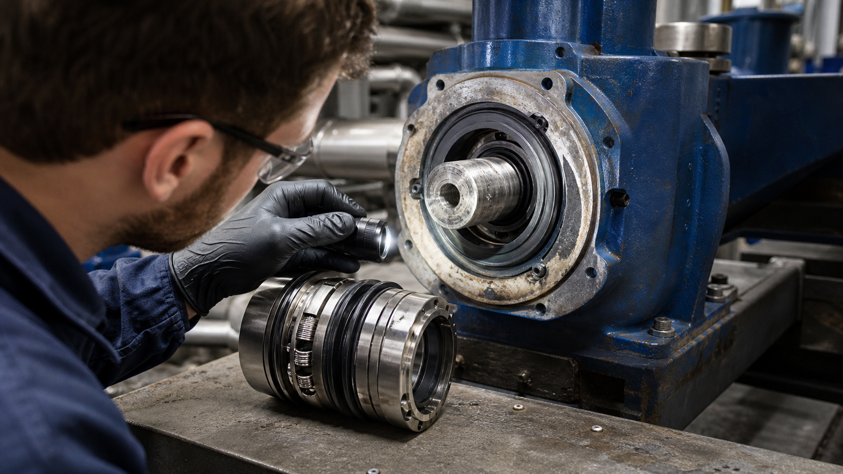
A mechanical seal in a centrifugal pump relies on a liquid film measured in microns between two polished faces rotating at shaft speed. This microscopic layer carries pumped fluid across the seal interface at a controlled rate—low enough to meet emission limits, high enough to lubricate the faces and prevent friction damage. When pressure, temperature, alignment, or fluid properties push the system outside the film’s stable operating window, the seal fails. Understanding how each component maintains that film, how seal arrangements respond to different duty conditions, and how to read failure evidence separates reliable installations from repeated downtime.
Key Takeaways
- The seal face interface depends on a stable microscopic liquid film; most failures trace to conditions that collapse or overheat that film rather than defective parts.
- Pusher seals use springs or bellows to maintain face contact during shaft motion; non-pusher seals rely on hydraulic pressure and tolerate shaft runout better.
- Single seals handle clean liquids at moderate pressure; double seals inject a barrier or buffer fluid when the process liquid is abrasive, toxic, volatile, or corrosive to seal materials.
- Balanced seal designs reduce closing force at elevated pressure by exposing only part of the seal face to system pressure, extending life when stuffing-box pressure exceeds typical unbalanced seal limits.
- Seal-face damage patterns—thermal checking, pitting, grooving, or discoloration—reveal the failure mechanism and guide corrective action more reliably than assuming installation error.
How a Mechanical Seal Controls Leakage
A mechanical seal creates a dynamic barrier between the pump interior and atmosphere by pressing two precision-lapped faces together—one rotating with the shaft, one fixed to the pump housing. The faces remain separated by a liquid film typically measured in microns; film thickness depends on seal design, face materials, and operating conditions. This film carries a controlled leakage rate across the interface. If the faces contact metal-to-metal, friction heat destroys the seal in minutes or seconds. If the gap widens beyond design limits, leakage exceeds acceptable limits and the seal’s service life shortens.
System pressure pushes the rotating face toward the stationary face while springs or hydraulic forces maintain contact during transient conditions. The liquid film thickness adjusts continuously to balance opening forces—system pressure acting on the seal’s hydraulic area and hydrodynamic lift from rotation—against closing forces from spring load and atmospheric pressure on the back side. Temperature rise from viscous shear in the film must remain below the fluid’s vaporization point at the seal interface; when vapor forms, the film collapses and the faces overheat.
Unlike packing, which allows visible dripping and requires periodic tightening, a mechanical seal operates in a self-regulating equilibrium. Small disturbances in shaft position, pressure, or temperature shift the film thickness but do not cause sudden failure unless they exceed the seal’s design envelope. This stability makes mechanical seals standard for duties where packing leakage is unacceptable—high-speed pumps, volatile or toxic fluids, clean rooms, or installations subject to emission regulations.
Stationary and Rotating Faces, Secondary Seals, Springs, and Drive Parts
The rotating face mounts to the pump shaft through a sleeve or directly onto the shaft surface, held in place by setscrews or a split collar. An elastomeric secondary seal—an O-ring, wedge ring, or V-ring—seals between the rotating face and shaft while allowing axial motion to follow shaft runout or thermal expansion. The stationary face sits in a gland plate bolted to the pump casing or stuffing box, sealed to the housing by a static O-ring or gasket.
Springs or a bellows apply closing force to the rotating assembly. Multiple coil springs distributed around the shaft or a single wave spring provide load across the seal face. A metal bellows, typically stainless steel, combines spring force with the secondary seal function in non-pusher designs. Spring materials and coatings must resist corrosion from the pumped fluid; in corrosive services, springs may be isolated from the process by a bellows or protective coating.
Drive lugs, pins, or a drive collar transmit torque from the shaft to the rotating face assembly without restricting axial float. The rotating face must follow shaft runout and thermal growth while maintaining contact with the stationary face. If drive lugs bind or corrosion locks the rotating assembly, the seal loses its ability to track shaft motion and face contact becomes uneven.
Face materials pair a hard surface—silicon carbide, tungsten carbide, or ceramic—against a counter-face, which may be carbon-graphite or a second hard material with different thermal expansion. The material combination must resist the specific fluid chemistry, temperature, and abrasive content. Silicon carbide against carbon works for clean water at moderate temperature; tungsten carbide against silicon carbide handles abrasive slurries; hard-face-to-hard-face pairs like silicon carbide against itself require excellent surface flatness and fluid lubricity to prevent chipping.
Pusher, Non-Pusher, Cartridge, Balanced, and Unbalanced Designs
Pusher seals use springs that push the rotating assembly along the shaft to maintain face contact. The springs sit outside the secondary seal, so fluid contact depends on secondary-seal integrity. Non-pusher seals integrate the spring function into a metal bellows that also serves as the secondary seal. The bellows flexes to accommodate shaft motion without sliding contact, making non-pusher seals more tolerant of shaft runout and eliminating the fretting wear that can occur at a pusher seal’s O-ring interface.
Cartridge seals arrive as a pre-assembled unit with the rotating face, stationary face, springs, secondary seals, and gland plate already set to the correct dimension. The installer mounts the entire cartridge onto the shaft and bolts the gland to the pump without measuring seal-face gaps or setting springs. This design reduces installation errors, speeds replacement, and ensures consistent performance when multiple seals in a plant are serviced by technicians with varying experience. Cartridge seals cost more than component seals but often pay back through reduced downtime and labor.
Balanced seals reduce the hydraulic closing force by limiting the area of the seal face exposed to system pressure. An unbalanced seal exposes the full seal face diameter to stuffing-box pressure, generating high unit loading at the face interface. As system pressure increases, face loading rises proportionally, accelerating wear and heat generation. A balanced seal uses a step or shoulder on the rotating face to create a smaller hydraulic area, so higher pressure produces only moderate closing force. Balance ratio—the ratio of hydraulic closing area to seal face area—is specified by the seal manufacturer based on pressure, speed, and fluid properties. Consult manufacturer selection charts for the pressure threshold where balanced seals become necessary for your specific seal size and operating conditions.
Single, Double, Tandem, and Pressurized Arrangements
Single seals place one mechanical seal between the pump interior and atmosphere. The seal faces run in the pumped fluid. This arrangement handles most clean-liquid duties where the fluid is non-toxic, non-volatile, and compatible with seal materials. If the pumped fluid contains abrasives, polymerizes at seal-face temperatures, or flashes to vapor at atmospheric pressure, a single seal will fail quickly.
Double seals install two mechanical seals in series with a barrier or buffer fluid circulating between them. In a back-to-back arrangement, both seals face outward into a pressurized chamber. Barrier fluid at higher pressure than the pump stuffing-box pressure flows across both seal faces; if either seal leaks, barrier fluid enters the pump or escapes to atmosphere rather than allowing process fluid to leak out. This protects against toxic, flammable, or environmentally hazardous fluids and keeps abrasive or polymerizing fluids away from the seal faces. In a face-to-face arrangement, both seals face inward; buffer fluid at lower pressure than stuffing-box pressure circulates between them. If the inboard seal leaks, process fluid enters the buffer reservoir rather than reaching the atmosphere. This arrangement costs less than back-to-back but does not prevent process contamination of the buffer system.
Tandem seals place two seals in series with the space between them vented to a low-pressure reservoir or atmospheric drain. The inboard seal handles normal duty; the outboard seal acts as a backup if the inboard seal fails. Tandem arrangements suit high-temperature services where a single seal would overheat or applications requiring low emissions but not justifying the cost and complexity of a pressurized double seal.
API 682 standardizes seal arrangements, piping plans, and barrier-fluid systems for petroleum and chemical services. Plan 52 circulates barrier fluid from an external reservoir through a back-to-back double seal; Plan 53 uses a pressurized bladder accumulator to maintain barrier pressure above stuffing-box pressure without pumps or controls. Plan 11 flushes a single seal from pump discharge; Plan 32 circulates fluid from an external source when the pumped fluid cannot cool or lubricate the seal. Consult the full standard or manufacturer documentation for complete piping schematics and component specifications.
Select by Fluid, Pressure, Temperature, Solids, and Shaft Motion
Seal selection starts with fluid properties: specific gravity, viscosity, vapor pressure, corrosivity, abrasive content, and tendency to crystallize or polymerize. A fluid with vapor pressure near or above stuffing-box pressure requires cooling, throttle bushings to raise seal-chamber pressure, or a double seal with compatible barrier fluid. Abrasive slurries demand hard face materials—tungsten carbide or silicon carbide—and flushing arrangements that keep solids away from the seal faces. Corrosive fluids require elastomer compatibility checks and may dictate exotic face materials or coatings.
Stuffing-box pressure determines whether an unbalanced or balanced seal is appropriate. Seal manufacturers publish selection charts that correlate seal size, shaft speed, and pressure to recommended designs. Face loading in an unbalanced seal increases directly with pressure; beyond the manufacturer’s stated limit, balanced seals reduce closing force and extend life.
Temperature limits depend on elastomer materials and fluid properties. Consult elastomer compatibility charts for maximum temperature ratings; common materials include Buna-N and EPDM for moderate temperatures, Viton for elevated temperatures, and Kalrez or FFKM for extreme heat. If stuffing-box temperature approaches the fluid’s boiling point at seal-chamber pressure, external cooling via Plan 21 (cooling jacket in the seal gland) or Plan 23 (external heat exchanger in a closed loop) prevents vapor formation and thermal distortion.
Shaft runout and end play must fall within seal tolerances specified by the manufacturer. Excessive runout opens the seal face on one side during each shaft revolution, pumping fluid across the interface and accelerating wear. Before installing a new seal, measure shaft runout with a dial indicator at the seal location; if runout exceeds seal limits stated in the installation instructions, correct the shaft condition or bearing clearances. Component seals typically require tighter runout control than cartridge or non-pusher designs; consult the seal datasheet for specific limits.
Read Seal-Face Damage before Blaming the Seal
Most seal failures leave evidence on the seal faces that reveals the root cause. Thermal checking—a pattern of fine radial cracks in the carbon face—indicates that the seal ran dry or overheated, collapsing the lubricating film. Causes include loss of flush flow, vapor locking, reverse rotation during startup, or running the pump with the suction valve closed. Thermal checking does not mean the seal was defective; it means operating conditions violated the seal’s thermal limits.
Blistering or pitting on the carbon face results from fluid flashing across the seal interface. When stuffing-box pressure drops near the fluid’s vapor pressure, localized boiling in the seal gap creates vapor pockets that collapse violently, eroding the carbon surface. This failure points to insufficient NPSHa, excessive suction lift, or a throttle bushing that dropped seal-chamber pressure below safe levels. Raising seal-chamber pressure with a flush from pump discharge or installing a Plan 11 or Plan 13 arrangement prevents recurrence.
Abrasive grooving—concentric wear tracks on both faces—means solids entered the seal chamber. If the pumped fluid is clean, the source may be installation debris, gasket material, or corrosion products from piping. If the fluid contains suspended solids, a cyclone separator (Plan 21), external flush (Plan 32), or throttle bushing to keep solids out of the seal chamber is required. Simply replacing the seal without addressing the solids source leads to identical failure.
Face chipping or fracture occurs when hard-face materials (silicon carbide or tungsten carbide) are shock-loaded during installation, experience thermal shock from rapid temperature swings, or encounter hydraulic transients. Improper handling, running the pump dry briefly, or water hammer in the piping system can crack the faces. Hard-face-to-hard-face combinations are especially vulnerable; switching to a hard-versus-soft pairing (silicon carbide versus carbon) improves shock resistance at the cost of slightly higher wear rates in abrasive service.
Discoloration or coking on the faces indicates chemical attack, polymerization, or excessive temperature. If the fluid is known to polymerize, a flush plan that introduces clean solvent or cool process fluid across the seal faces prevents buildup. If discoloration is uniform and black, the fluid may have exceeded its thermal stability limit at seal-face temperatures; reducing face loading with a balanced seal or improving cooling resolves the problem.
Installation and Failure-Prevention Checklist
Before installing a seal, verify shaft condition: measure runout, check for burrs or damage at the seal location, and confirm that keyways are smooth. Clean the shaft and seal chamber thoroughly; even small particles can damage the seal faces during initial operation. Do not touch seal faces with bare hands; skin oils and fingerprints create hot spots and accelerate wear.
Lubricate O-rings and gaskets with a compatible lubricant—glycerin or soapy water for water service, light oil for petroleum products. Do not use grease unless specified by the seal manufacturer; grease can trap particles or react with the pumped fluid. Install O-rings without twisting or pinching; a twisted O-ring leaks immediately.
Set seal-face gaps and spring compression per the manufacturer’s instructions. For component seals, this usually involves measuring from a fixed reference point on the shaft to the seal face or gland. Incorrect dimensions cause the faces to run open (excessive leakage) or jammed together (rapid wear). Cartridge seals eliminate this measurement but require correct shaft preparation and spacer installation per the supplied drawing.
Flush and vent the seal chamber before starting the pump. Trapped air causes dry running and thermal damage. For double seals, fill and pressurize the barrier system, verify circulation through sight glasses or flow indicators, and confirm that barrier pressure exceeds stuffing-box pressure by the margin specified in the seal documentation.
Align the pump and driver within coupling manufacturer tolerances before declaring the installation complete. Misalignment loads the seal faces unevenly, accelerates wear, and can bend the shaft enough to exceed seal runout limits. Check alignment after piping is connected and the system is at operating temperature; thermal growth shifts alignment from the cold condition.
FAQs
What causes a mechanical seal to fail within days of installation?
Immediate failure usually traces to installation errors—incorrect seal-face gap, damaged O-rings, debris on seal faces, or inadequate shaft preparation. If the seal was installed correctly, check for dry running (no liquid in the pump during startup), reverse rotation, or a closed suction valve. Read the seal faces for thermal checking, pitting, or abrasive damage to identify the specific cause rather than assuming the seal was defective.
Can a single mechanical seal be upgraded to a double seal without changing the pump?
Most pumps accept double seals if the stuffing box is deep enough and the gland can be modified or replaced. The barrier-fluid system requires additional piping, a reservoir, and possibly a circulation pump or heat exchanger depending on the plan selected. Measure the available axial space on the shaft and consult seal manufacturers’ dimensional data to confirm compatibility before ordering parts.
How do you calculate the correct barrier-fluid pressure for a double seal?
Barrier pressure must exceed maximum stuffing-box pressure by a margin sufficient to ensure inward flow across the inboard seal face even during transient conditions. Seal manufacturers specify required pressure differentials based on seal design and operating conditions. Measure stuffing-box pressure directly with a gauge installed in the seal chamber rather than assuming it equals discharge pressure; throttle bushings and other restrictions can create significant pressure drops.
Why does a seal leak only during startup or shutdown?
Transient leakage often results from thermal expansion mismatch between the rotating and stationary seal components. During startup, the rotating face heats faster than the stationary face, temporarily opening the seal gap until thermal equilibrium is reached. Using materials with similar thermal expansion coefficients or allowing a brief warm-up period before bringing the pump to full speed reduces transient leakage. Persistent leakage after reaching steady-state operating temperature indicates incorrect seal selection or installation errors.
When should seal faces be lapped or replaced instead of reused?
If seal faces show thermal checking, pitting, grooving, chips, or cracks, replace them. Minor surface staining or light wear may be acceptable if the faces remain flat within the limits specified by the seal manufacturer when checked with an optical flat. Lapping restores flatness but removes material; if wear has already reduced face thickness near minimum limits specified by the manufacturer, replacement is safer. Always replace elastomeric secondary seals during rebuild; O-rings take a compression set and do not seal reliably after removal.
Conclusion
Centrifugal pump mechanical seal selection and diagnosis depend on matching seal design and arrangement to measured fluid properties, system pressure, temperature, and shaft condition rather than assuming one seal type fits all duties. Record stuffing-box pressure, temperature, shaft runout, and fluid properties during commissioning and compare them to seal manufacturer limits. When failures occur, inspect the seal faces for thermal checking, pitting, abrasive wear, or chemical attack before ordering a replacement; the damage pattern identifies the operating condition that must change. For complex duties involving abrasive slurries, high pressure, toxic fluids, or repeated failures, request seal manufacturer assistance with full process data, pump curves, and operating logs to specify the correct arrangement and piping plan.