
title: "Centrifugal Pump Priming: Methods, Procedure, and Problems"
description: "Plan the installation sequence, piping, alignment, electrical checks, startup, and commissioning records needed for reliable service."
An electric motor turns a pump shaft while the impeller spins inside a casing full of air. The blades accelerate the air and discharge it through the volute, but the pump produces almost no pressure and moves no water. Air at atmospheric conditions weighs roughly one eight-hundredth the density of water, so the centrifugal force developed by the rotating impeller cannot create enough head to lift liquid from a lower reservoir or overcome system resistance. The pump runs without moving liquid until the casing and suction line are filled.
Centrifugal pump priming is the process of filling the pump casing and suction piping with liquid and removing trapped air before starting the driver. Without priming, the pump cannot establish the hydraulic conditions needed to develop rated head and flow. Most standard centrifugal pumps require an external method to fill the suction side and establish liquid continuity from the source to the impeller eye. This article explains why centrifugal pumps need priming, describes common priming methods, provides a commissioning procedure, and covers diagnosis of repeated loss of prime.
Key Takeaways
- Centrifugal pumps cannot develop useful head when the casing is full of air because air density is approximately one eight-hundredth that of water at standard conditions.
- Standard installations require manual filling through the casing vent, a foot valve, vacuum priming, or an external ejector system before the driver is started.
- Self-priming centrifugal pumps use an enlarged casing reservoir and internal recirculation to separate air and establish prime automatically, but they still require initial liquid charge.
- Loss of prime after successful operation indicates suction-side air leaks, vortexing at low submergence, cavitation from insufficient NPSHa, or obstruction in the suction line.
- Verify suction pressure gauge reading, confirm rotation direction, and check vent valve closure before concluding the pump is primed.
Why Most Centrifugal Pumps Cannot Pump Air Effectively
A centrifugal pump relies on the rotating impeller to impart kinetic energy to the liquid, which is converted to pressure energy in the volute or diffuser. The head developed by the impeller is proportional to the tangential velocity squared:
H = (u₂² – u₁²) / (2g)
Where:
- H = head developed, m or ft
- u₂ = tangential velocity at impeller outlet, m/s or ft/s
- u₁ = tangential velocity at impeller inlet, m/s or ft/s
- g = gravitational acceleration, 9.81 m/s² or 32.2 ft/s²
This equation applies regardless of fluid, but the pressure developed depends on fluid density:
ΔP = ρ × g × H
Where:
- ΔP = pressure rise, Pa or psi
- ρ = fluid density, kg/m³ or lb/ft³
Air at atmospheric conditions weighs approximately one eight-hundredth as much as water. For the same head developed by the impeller, the pressure rise when pumping air is roughly one percent or less of the pressure rise when pumping water. A pump designed to develop substantial water head produces minimal pressure when pumping air—not enough to lift water from a suction source below the pump centerline or overcome friction losses in the discharge piping.
The pump runs without impeller damage, but it moves negligible liquid volume. In flooded-suction installations where the liquid source is above the pump, air trapped in the casing still prevents proper flow because the impeller cannot displace the air mass effectively. The pump must be filled with liquid to establish the density needed for normal hydraulic performance.
What Must Be Filled before Startup
Complete priming requires filling three hydraulic zones:
Suction piping volume: The entire pipe run from the liquid source to the pump suction flange must be filled. For installations drawing from a tank or reservoir below grade, this includes the vertical lift section and horizontal runs. Air pockets in high points prevent liquid from reaching the pump even when the casing is filled.
Pump casing volume: The space between the suction flange, impeller shrouds, and discharge flange must contain liquid. Standard end-suction and horizontal split-case pumps have casing volumes ranging from a few liters for small units to hundreds of liters for large process pumps. Vertical turbine and submersible pumps prime automatically when installed below the liquid level, but the column pipe and bowl assembly must still be vented during initial fill.
Impeller eye and wear ring clearance: The narrow annular gap between the impeller hub and the suction-side wear ring must be wetted for the pump to develop pressure. If air remains in this zone, the impeller recirculates air instead of liquid, and internal leakage through the wear ring clearance prevents pressure buildup even when the rest of the casing is filled.
For pumps equipped with mechanical seals, the seal chamber must also be flushed and vented. Dry running causes immediate seal face damage from friction and heat. Seal manufacturers specify minimum flush flow rates and pressure conditions; consult the seal data sheet for the specific requirements of your installation.
Manual Filling, Foot Valve, Vacuum, Ejector, and Self-Priming Methods
Five methods cover most industrial priming applications:
Manual Filling through Casing Vent
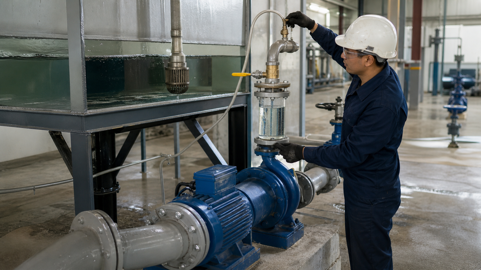
The pump casing includes a threaded vent plug or valve at the high point, typically on the volute or discharge flange. With the suction valve open and a foot valve or closed suction valve maintaining liquid in the suction line, the operator removes the vent plug and pours liquid into the casing through the suction or a dedicated priming port until liquid flows from the vent. The vent plug is reinstalled, the suction valve is opened if it was closed, and the pump is started. This method requires the suction line to remain flooded between starts, either through a foot valve at the suction inlet or because the liquid source is above the pump.
Foot Valve with Manual Fill
A foot valve is a check valve installed at the bottom of the suction pipe, submerged in the liquid source. It allows liquid to enter the suction line during priming but prevents backflow when the pump stops, keeping the suction pipe and casing filled between operating periods. Manual filling proceeds as described above. Foot valves introduce additional head loss, which must be included in the NPSHa calculation. The magnitude depends on valve size, design, and flow rate; consult the valve manufacturer’s performance curve. The valve seat must seal tightly to prevent air entry.
Vacuum Priming System
A vacuum pump or ejector removes air from the pump casing and suction line, creating a pressure differential that draws liquid from the source. The vacuum priming system connects to a tapping on the pump casing or discharge piping through a separator pot that collects expelled air and liquid. When the casing is filled and liquid reaches the separator, a level switch or manual observation signals priming completion. The vacuum source is isolated, and the pump driver is started. Vacuum priming is common for large pumps, pumps with long suction lines, and installations where manual filling is impractical.
External Ejector Priming
An ejector uses high-pressure motive water from another source to create suction through venturi action. The ejector connects to the pump casing vent line, and the motive flow entrains air and discharges it to a drain or collection point. Once liquid flow is established, the ejector is shut off and the pump operates normally. Ejector priming offers faster air removal than manual filling and does not require a separate vacuum pump, but it consumes motive water and requires a reliable high-pressure source.
Self-Priming Centrifugal Pumps
Self-priming centrifugal pumps feature an enlarged casing reservoir that retains liquid between operating cycles and an internal recirculation chamber where air and liquid are separated during startup. When the pump is started with air in the suction line, the impeller recirculates the stored liquid, creating a low-pressure zone that gradually draws liquid from the source while air is vented to the discharge. The separation chamber allows air bubbles to rise and exit while liquid returns to the impeller suction, progressively replacing air with liquid until the suction line is filled and normal pumping begins.
Self-priming pumps require an initial liquid charge to fill the reservoir—they cannot start from a completely empty casing. Priming time depends on suction lift, suction line diameter, and air volume to be evacuated. Self-priming capability typically decreases as head increases; consult the pump curve for the maximum suction lift at your operating point. Self-priming designs cost more and operate at slightly lower efficiency than standard centrifugal pumps, but they eliminate manual priming steps in applications with frequent starts and potential air entry.
A Safe Priming and Venting Procedure
This procedure applies to standard end-suction and horizontal split-case pumps with manual priming. Adjust steps to match the specific pump design, piping layout, manufacturer instructions, and site safety rules.
Pre-priming inspection:
- Verify that the driver is electrically isolated and locked out.
- Confirm that all suction and discharge piping is complete, flushed, and free of debris.
- Check that the pump base is grouted, anchor bolts are torqued per the installation drawing, and coupling alignment is within the manufacturer’s tolerance.
- Verify that all pressure gauges, temperature sensors, and instrumentation are installed and valved in.
- Inspect mechanical seal piping for correct connection and flush valve position.
Fill the suction line:
- If a foot valve is installed, verify that the suction source level is adequate and the foot valve strainer is submerged.
- Slowly open the suction isolation valve, allowing liquid to fill the suction pipe. For long or large-diameter suction lines, open the valve incrementally to avoid water hammer.
- If the suction line has a high point or loop, open any air release valves along the line and close them when liquid appears.
Fill the pump casing:
- Confirm the discharge valve is closed. Starting a centrifugal pump against a closed discharge valve is standard commissioning practice; the pump is not damaged by brief operation at shutoff head.
- Remove the casing vent plug or open the vent valve at the pump’s high point.
- Pour clean liquid matching the process fluid into the casing through the suction flange or a dedicated priming tapping. For process pumps handling chemicals or high-temperature liquids, use the actual process liquid to avoid thermal shock or contamination.
- Continue filling until liquid flows steadily from the vent, indicating that the casing and impeller region are full and air is displaced.
- Reinstall the vent plug or close the vent valve. For pumps with mechanical seals, verify that the seal flush line is open and liquid is circulating through the seal chamber.
Prepare for startup:
- Remove lockout-tagout devices and restore electrical power.
- Confirm that the driver rotates in the correct direction by jogging or momentarily bumping the starter. An arrow on the pump casing or coupling guard indicates the required rotation direction.
- Verify that all vent and drain valves are closed and pressure gauges are valved in.
- Open the suction valve fully if it was throttled during filling.
Start and verify:
- Start the driver and observe the suction pressure gauge. A properly primed pump shows a steady reading appropriate for the installation—negative gauge pressure (suction below atmospheric) for suction-lift configurations or positive gauge pressure for flooded-suction installations.
- Slowly open the discharge valve to establish flow. Monitor the discharge pressure gauge for steady pressure rise as the valve opens.
- Check for leaks at all flanges, seal glands, and valve packing.
- Listen for abnormal noise or vibration that might indicate cavitation, air entrainment, or mechanical problems.
If the pump does not develop pressure or the discharge pressure drops immediately after startup, shut down and repeat the priming procedure. Do not operate a centrifugal pump for extended periods without liquid flow—this causes seal damage and bearing overheating even if the casing is filled.
Prove Suction Integrity before Starting
Before concluding that a pump is primed, confirm that the suction side holds vacuum or positive pressure and that no air leaks allow re-entry after filling. Three verification methods are used:
Suction pressure gauge test: Install a compound gauge (vacuum and pressure scale) on the pump suction flange or suction piping near the pump. After filling the casing and suction line, close the suction valve and observe the gauge. If the pressure rises toward atmospheric over several minutes, air is entering through a leak in the suction piping, pump casing gasket, or mechanical seal. For pumps with flooded suction, a positive pressure should remain steady.
Liquid level observation: For pumps with sight glasses or open priming ports, verify that the liquid level in the casing remains constant after filling. A falling level indicates air displacement of liquid or leakage past the suction valve or foot valve.
Rotation direction check: Even a fully primed pump will not develop pressure if the impeller rotates backward. Three-phase motors reverse direction if two supply leads are swapped. Check rotation before starting under load by momentarily jogging the motor and observing the coupling or shaft through the guard opening. The correct direction is marked on the pump casing. Backward rotation produces minimal pressure and can be mistaken for lack of prime.
Air Leaks, Blockage, Wrong Rotation, and Repeated Loss of Prime
Loss of prime after successful operation points to a change in suction conditions or system integrity. Diagnose using this fault tree:
Suction-side air leaks: Loose flange bolts, damaged gaskets, worn mechanical seal faces, or cracked piping allow air to enter when the suction operates under vacuum. Leaks often appear as air bubbles in discharge flow or erratic pressure gauge readings. Soap solution applied to suspected joints reveals leaks during operation. Repair by retorquing bolts to the gasket manufacturer’s specification, replacing damaged gaskets, or overhauling the mechanical seal.
Vortexing at low submergence: When the liquid level in the suction tank or reservoir drops below the minimum submergence depth for the suction inlet, a surface vortex forms and draws air into the pipe. Minimum submergence depends on inlet diameter and flow velocity; consult the piping design standard or pump manufacturer’s installation drawing for the required depth. Install a level switch to prevent pump operation below the minimum safe level, or add a vortex breaker at the inlet.
Cavitation from insufficient NPSHa: Severe cavitation produces vapor bubbles that are swept into the impeller eye and collapse, creating noise, vibration, and erratic performance that resembles air binding. Check the system NPSHa calculation against the pump’s NPSHr at the actual operating point on the certified pump curve. If NPSHa is marginal, reduce suction line losses, increase submergence, lower liquid temperature, or install a booster pump to raise suction pressure.
Blockage in suction strainer or foot valve: Debris accumulation increases suction line losses, reduces flow, and may allow air pockets to form in the suction pipe. Inspect and clean the strainer and foot valve. If blockage recurs frequently, verify that the strainer mesh size is appropriate for the liquid and that upstream filtration is adequate.
Foot valve leakage: A foot valve that does not seal completely allows the suction line to drain back to the source when the pump stops. Priming succeeds initially, but the pump loses prime between starts. Replace the foot valve or disassemble and clean the valve seat if debris is preventing closure.
Wrong impeller direction: If the pump operated correctly and then lost prime after maintenance or electrical work, verify rotation direction. A motor that was reconnected with two phases reversed will run backward, producing minimal head and no flow.
Priming Method Selection by Installation Layout
Installation Type | Priming Method | Advantages | Limitations |
|---|---|---|---|
Flooded suction, liquid source above pump | Manual vent, pump runs when valve opens | No foot valve or vacuum system needed; fastest startup | Not applicable to suction lift installations |
Low to moderate suction lift, frequent starts | Self-priming pump with reservoir | Automatic re-priming; no external equipment | Higher initial cost; lower efficiency; lift capability limited by model |
Suction lift, infrequent starts | Foot valve with manual fill | Low cost; simple operation | Foot valve head loss reduces NPSHa; valve may leak over time |
High suction lift or long suction line | Vacuum priming system | Handles large air volume; reliable | Requires vacuum pump or plant air supply; higher installation cost |
Process pumps, hazardous liquids | Closed-system vacuum or ejector | No manual access to casing; safe for toxic or flammable fluids | Requires instrumentation and interlocks; higher complexity |
For new installations, verify suction lift, source level variation, and start frequency before selecting the priming method. Self-priming pumps suit applications with moderate suction lift and daily or more frequent starts; consult the pump curve for the maximum lift at your duty point. Flooded suction layouts avoid priming complexity and maximize NPSHa but require the liquid source to be elevated above the pump or the installation to be located in a sump or pit. Vacuum priming systems add cost but provide reliable, repeatable priming for large pumps and difficult installations.
FAQs
Can a centrifugal pump prime itself if you run it long enough?
No. Standard centrifugal pumps cannot self-prime regardless of run time. The impeller recirculates air without developing enough pressure to lift liquid from the source. Running the pump dry causes mechanical seal damage and bearing overheating within minutes. Only pumps specifically designed as self-priming, with an internal reservoir and air separation chamber, can establish prime automatically.
How do you prime a centrifugal pump with high suction lift?
Manual filling through a foot valve becomes impractical at high suction lift because atmospheric pressure limits the maximum theoretical water column height at sea level, and suction line losses reduce the effective lift further. Use a vacuum priming system to evacuate air from the casing and suction line, or install a self-priming centrifugal pump rated for the required lift. Alternatively, relocate the pump closer to the liquid source or install the source tank above the pump to create a flooded suction. Consult the pump manufacturer for the maximum suction lift at your operating point.
What is the difference between priming and venting a pump?
Priming is the process of filling the pump casing and suction line with liquid before startup, ensuring that liquid reaches the impeller eye. Venting is the removal of trapped air from the casing high points during and after priming. Both are necessary for complete commissioning: priming establishes liquid continuity, while venting removes residual air pockets that prevent proper flow even when most of the system is filled.
Does a centrifugal pump need to be primed every time it starts?
Only if the pump loses prime between starts. Pumps with foot valves or flooded-suction installations maintain liquid in the casing and suction line after shutdown, so they start immediately without re-priming. Pumps that drain back to the source when stopped require priming before each start unless a self-priming design is used. Check the suction pressure gauge before starting; if it shows vacuum or positive pressure, the pump is still primed.
Why does my centrifugal pump lose prime during operation?
Loss of prime during operation indicates either air entry through a suction-side leak, vortexing at the suction inlet due to low liquid level, or severe cavitation that produces large vapor volumes at the impeller eye. Inspect suction piping flanges and gaskets for air leaks, verify that the liquid level remains above the minimum submergence depth specified in the installation drawing, and confirm that NPSHa exceeds NPSHr by the margin shown on the pump curve. If cavitation is the cause, reduce suction losses or increase suction pressure.
Conclusion
Centrifugal pump priming transforms a spinning impeller in an air-filled casing into a working pump that delivers rated flow and head. The priming method must match the installation layout, suction lift, and operating frequency, and the procedure must verify suction integrity before startup to prevent dry running and seal damage. After successful priming and commissioning, record the suction and discharge pressure readings, motor current, and flow rate at the rated duty point as the baseline for future troubleshooting. If repeated loss of prime occurs, diagnose using the suction integrity tests and fault tree provided, and confirm that system NPSHa remains adequate across the operating envelope. For new installations where priming method selection affects pump choice and piping design, compare the cost and reliability tradeoffs in the layout table against your site’s maintenance resources and start frequency requirements.