
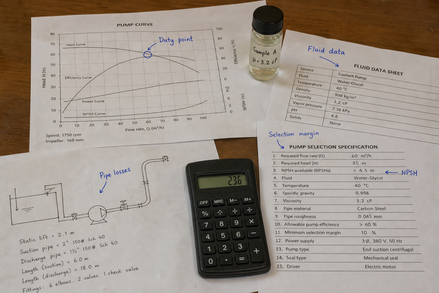
Field-style article image prepared for centrifugal pump sizing process requirements.
When a chemical processing line experiences flow shortfalls or pressure drops during peak demand, the root cause often traces back to incomplete sizing data at the specification stage. Centrifugal pump sizing requires three categories of process requirements: the duty point that defines the operating condition, the fluid property dataset that governs hydraulic performance and material compatibility, and the curve margin that accommodates system variation and future capacity.
A properly sized centrifugal pump delivers the required flow rate at the specified head under actual operating conditions while maintaining efficiency within an acceptable range. The sizing process translates system needs into pump selection parameters, accounting for both steady-state operation and transient conditions that affect performance throughout the pump’s service life.
Key Takeaways
- The duty point combines required flow rate and total dynamic head as the primary sizing coordinate on the pump performance curve
- Fluid properties including density, viscosity, vapor pressure, and temperature directly affect head conversion, power requirements, and NPSH available
- Pump curve margin between the duty point and best efficiency point determines how the pump responds to system resistance changes and wear over time
- Installation geometry, piping losses, and control methods establish the system curve that intersects the pump curve at the operating point
- Material selection and seal type depend on fluid chemistry, temperature limits, and solids content identified during the sizing process
Establishing the Duty Point
The duty point represents the flow rate and total dynamic head the pump must deliver at the specified operating condition. Flow rate comes from the process requirement, typically expressed in gallons per minute (GPM), cubic meters per hour (m³/h), or liters per second (L/s). Total dynamic head (TDH) equals the sum of static head, friction losses, pressure head differential, and velocity head.
Static head measures the vertical elevation difference between the suction and discharge liquid levels. This value remains constant regardless of flow rate and forms the baseline head requirement. For a pump drawing from a ground-level tank and discharging to a vessel 30 feet above, the static head is 30 feet.
Friction losses accumulate through piping, fittings, valves, and equipment. These losses increase with the square of velocity and must be calculated for the actual pipe sizes, lengths, and materials in the installation. A system with 150 feet of 4-inch Schedule 40 pipe, six 90-degree elbows, and two gate valves requires detailed friction calculations at the design flow rate.
Pressure head differential converts any pressure difference between suction and discharge vessels into equivalent head. When pumping from an atmospheric tank to a vessel at 25 psig, the pressure head adds 57.7 feet (25 psi × 2.31 ft/psi for water). The conversion factor changes with specific gravity for other fluids.
Fluid Property Data Requirements
Specific gravity determines the relationship between head and pressure, affecting both the head calculation and the power requirement. A pump moving water (SG = 1.0) and the same pump moving a hydrocarbon (SG = 0.7) develop the same head in feet, but the hydrocarbon application requires only 70% of the power. The brake horsepower calculation multiplies flow, head, and specific gravity, making density errors costly.
Viscosity affects pump performance by reducing capacity, head, and efficiency compared to the published water-based curve. Fluids above 100 SSU (Saybolt Universal Seconds) require correction factors applied to the water performance curve. The Hydraulic Institute provides correction charts that reduce rated capacity and head as viscosity increases. A pump rated for 500 GPM at 100 feet with water might deliver only 450 GPM at 85 feet when pumping a 500 SSU fluid.
Vapor pressure at pumping temperature establishes the NPSH required calculation and determines cavitation risk. The NPSH available must exceed NPSH required by an adequate margin, typically 3 to 5 feet minimum. For volatile fluids like propane, ethanol, or heated water near saturation, vapor pressure dominates the suction system design and may force larger suction piping or reduced suction lift.
Temperature affects both fluid properties and material limits. Elastomer seals, packing materials, and bearing lubricants each have maximum temperature ratings. Thermal expansion of the casing and shaft must be accommodated in the bearing housing design for fluids above 200°F. Cold fluids below 0°F may require special metallurgy to prevent brittle fracture.
Solids content and particle size determine impeller design, clearance requirements, and seal selection. Fluids with abrasive solids need hard-face seal materials, larger clearances, and possibly semi-open or open impellers. Non-abrasive fibrous content may require vortex or recessed impellers that pass solids without clogging.
Pump Curve Margin and Selection Criteria
The pump performance curve plots head versus flow, with the duty point ideally positioned between 80% and 110% of the flow at best efficiency point (BEP). Operating too far left of BEP increases radial thrust and recirculation, causing vibration and premature wear. Operating too far right reduces efficiency and may approach the minimum continuous flow limit where thermal issues develop.
Curve shape determines stability when system resistance varies. A flat curve delivers nearly constant head across a wide flow range, useful for systems with uncertain friction losses or parallel pump operation. A steep curve provides better flow control and more predictable performance but less tolerance for system changes.
The shut-off head to rated head ratio indicates how the pump responds when a discharge valve closes. A pump with 120 feet shut-off head and 100 feet rated head has a 20% rise to shut-off. High ratios increase the stress on seals and may require pressure relief protection. Low ratios indicate a drooping curve that may not meet head requirements if system resistance increases.
Power curve slope determines whether the pump is non-overloading. A non-overloading characteristic shows maximum power near BEP, with power decreasing toward higher flows. This protects the motor from overload if the discharge pressure drops unexpectedly. Overloading curves increase power toward higher flows and require motor selection based on the power at maximum flow, not at the duty point.
System Curve Integration
The system curve represents the total head requirement as a function of flow rate. Static head forms the y-intercept, while friction losses create the parabolic increase with flow. The operating point occurs where the pump curve intersects the system curve, and this point may differ from the specified duty point if the curves were calculated incorrectly.
Parallel pump operation flattens the combined pump curve at low flows where individual pumps operate near shut-off. The crossover point where two pumps become more efficient than one pump depends on the individual pump curve shape and the system curve slope. Sizing for parallel operation requires confirming that each pump operates within its acceptable range when one pump is out of service.
Variable speed drive control changes the pump curve family, with head varying as the square of speed and power varying as the cube. A pump sized for 1750 RPM operation that runs at 1400 RPM delivers 64% of rated head and requires only 41% of rated power. The duty point must be achievable within the VFD speed range while keeping the minimum speed above the point where motor cooling becomes inadequate.
Installation and Control Factors
Suction piping design affects NPSH available and determines whether the pump can operate without cavitation. The suction line should be one to two pipe sizes larger than the pump suction connection, with a straight run of 5 to 10 pipe diameters before the pump inlet. Eccentric reducers with the flat side up prevent air pockets that would reduce NPSH available.
Control method influences the duty point specification. A throttle valve control system requires the pump to operate at higher head with the valve partially closed, wasting energy as friction loss. A bypass control returns excess flow to the suction vessel, maintaining constant pump flow but requiring heat removal for the recirculated fluid. Variable speed control tracks the system curve and provides the most efficient operation but adds cost and complexity.
Duty cycle affects the allowable temperature rise at minimum flow. Continuous operation requires a minimum flow bypass that removes heat generated by hydraulic losses and keeps fluid temperature below limits. Intermittent operation may tolerate short periods at reduced flow without thermal protection. The minimum continuous stable flow, typically 40% to 60% of BEP flow, sets the lower limit for sustained operation.
Future capacity requirements may justify oversizing by 10% to 25% in flow or head. This margin accommodates process changes, piping modifications, or additional equipment downstream. However, excessive oversizing forces the pump to operate far from BEP, reducing efficiency and reliability. A staged approach with space for a second pump often proves more economical than large single-pump oversizing.
FAQs
How do you account for liquid temperature changes during pump operation?
Calculate fluid properties at the maximum expected pumping temperature, not the average or nominal condition. Viscosity, vapor pressure, and density all vary with temperature, and sizing for the worst-case condition prevents cavitation or inadequate head at elevated temperatures. For fluids that heat up significantly during recirculation or deadhead conditions, include this temperature rise in the NPSH available calculation.
What sizing margin should be added for pump wear over time?
A 5% to 10% margin in head accounts for wear ring clearance increases and impeller damage that accumulate during service. This margin keeps the worn pump above minimum acceptable performance without forcing oversizing that reduces initial efficiency. Systems with abrasive fluids or severe service may require 15% margin and more frequent maintenance intervals to restore performance.
Does the sizing process change for hazardous or sanitary applications?
The fundamental hydraulic sizing remains the same, but material selection, seal type, and code compliance add requirements beyond basic duty point calculations. Hazardous fluids may mandate sealless pumps (magnetic drive or canned motor) that eliminate shaft seal leakage risk. Sanitary applications require specific surface finishes, drainable designs, and materials compatible with cleaning chemicals, but the flow and head calculation follows standard methods.
Conclusion
Centrifugal pump sizing requires complete process data across three categories: the duty point that defines required flow and head, the fluid properties that govern performance and materials, and the curve margin that positions operation relative to best efficiency. Gather system layout drawings, calculate friction losses with actual pipe sizes, measure or specify fluid properties at operating temperature, and verify that NPSH available exceeds NPSH required with adequate margin. The sized pump should operate between 80% and 110% of BEP flow under normal conditions, with enough head margin to accommodate wear and system changes without forcing operation into unstable regions of the performance curve.