
title: "Effluent Pump vs Sewage Pump: Which One Do You Need?"
description: "Compare operating principles, performance ranges, installation needs, solids handling, maintenance, and selection tradeoffs."
An effluent pump moves pre-treated liquid from a septic tank to a drain field or treatment unit, while a sewage pump handles raw wastewater containing solids directly from building drains. The distinction determines impeller geometry, passage clearance, and control strategy. Downstream of a septic tank, most settleable solids have dropped out, allowing the effluent pump to use narrower passages and run at higher cycling frequencies. A sewage pump must pass larger debris, which requires a semi-open or vortex impeller and a motor sized for intermittent high loads. Choosing the wrong pump leads to clogs, seal failures, and shortened bearing life.
Key Takeaways
- Effluent pumps sit downstream of septic tanks and handle clarified liquid; sewage pumps take raw wastewater with solids from toilets, sinks, and drains.
- Impeller design differs: effluent pumps use closed or semi-open impellers with tighter passages; sewage pumps require vortex or single-vane designs for larger debris.
- Head and flow vary by system: check the manufacturer’s pump curve against your calculated total dynamic head and required flow rate.
- Control logic ranges from simple on/off float switches for effluent duty to high-level alarms and duplex alternating for sewage service.
- Swapping pump types causes clogging when an effluent pump meets raw sewage, or short-cycling and seal wear when a sewage pump runs in clean effluent.
- Selection depends on measured solids size, total dynamic head from the system curve, duty cycle, and whether the basin receives raw sewage or septic tank overflow.
Effluent and Sewage Pumps Handle Different Waste Streams
The waste stream defines the pump. Sewage is the combined discharge from toilets, showers, sinks, washing machines, and floor drains. It contains fecal matter, toilet paper, food particles, hair, grease, detergents, and other materials that enter the plumbing. Solids range from fine suspended particles to objects several inches across. A sewage pump must handle this mixture without pre-screening.
Effluent is the liquid that overflows from a septic tank after primary settling. Inside the tank, heavy solids settle to the bottom as sludge, and lighter materials float to the surface as scum. The middle layer of clarified liquid flows out through a submerged outlet baffle. While effluent still contains bacteria, dissolved organics, and fine suspended solids, the larger particles have been removed. Effluent solids content and particle sizes depend on septic tank condition and residence time.
This separation step changes the mechanical requirements. An effluent pump can use narrower passages and tighter impeller clearances because the risk of large objects entering the inlet is lower. A sewage pump cannot make that assumption.
Where Each Pump Sits in the Treatment System
A sewage pump is installed in a collection basin or sump that receives raw wastewater directly from building drains. Typical installations include:
- Basement bathroom ejector pits below the main sewer line
- Lift stations serving multiple buildings in low-lying areas
- Grinder pump vaults at individual homes in pressure-sewer systems
- Temporary bypass pumping during sewer repairs
The pump runs when the liquid level rises above the start float. Discharge goes into a gravity sewer, force main, or treatment plant headworks.
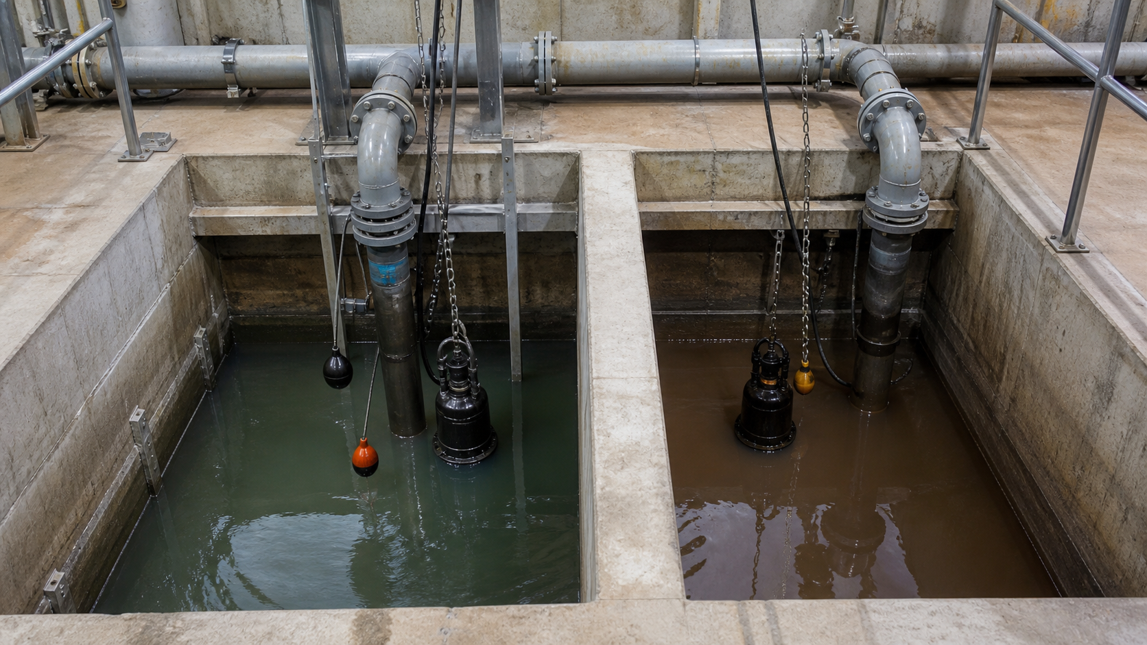
An effluent pump sits in the outlet chamber of a septic tank or in a separate dosing tank. The tank outlet is positioned below the inlet invert to ensure that clarified liquid reaches the pump. Discharge goes to one of three destinations:
- Gravity drain field: The pump delivers effluent to distribution laterals on a hillside or elevated bed where gravity cannot provide sufficient head.
- Pressurized drain field: Low-pressure pipes with orifices distribute effluent across a shallow bed. The pump must overcome friction losses in the distribution network.
- Secondary treatment unit: Advanced treatment systems require controlled dosing, which the effluent pump and timer controls provide.
Because effluent pumps often dose intermittently rather than running continuously, the duty cycle and thermal load on the motor differ from sewage service.
Solids Size, Passage, Impeller, and Screen Requirements
Maximum solids size drives impeller selection and passage geometry. Sewage pumps must pass larger solids without clogging. Effluent pumps handle smaller particles. The table below compares typical requirements; consult manufacturer specifications for your application:
Parameter | Effluent Pump | Sewage Pump |
|---|---|---|
Solids passage | Narrower passages for pre-settled liquid | Wider passages for raw wastewater |
Impeller type | Closed or semi-open, multiple vanes | Semi-open, single-vane, or vortex |
Inlet screen | Optional bar screen | None or coarse trash rack only |
Typical flow range | Lower, intermittent dosing | Higher, responsive to fixture use |
Typical head range | Varies with drain field distance and elevation | Varies with lift station geometry |
Material | Cast iron, stainless steel, thermoplastic | Cast iron, ductile iron, stainless steel |
Impeller geometry determines solids-handling capability and efficiency. A closed impeller with shrouds on both sides and narrow passages delivers higher efficiency but clogs more easily. Effluent pumps use closed or semi-open impellers because the liquid has been pre-settled. A semi-open impeller has vanes on one side only, allowing slightly larger solids to pass. A single-vane impeller is a thick blade that creates a pumping action with minimal obstruction; it passes fibrous material more reliably. A vortex impeller is recessed behind the inlet, creating a spinning vortex that carries solids through without contacting the impeller itself. Vortex designs sacrifice efficiency but clog less frequently, making them common in sewage service.
Inlet screens are sometimes used on effluent pumps to protect the impeller from occasional debris, but they add maintenance. Sewage pumps generally avoid inlet screens because they would clog faster than the pump itself. Instead, the pump chamber may include a coarse trash rack to catch bottles and other gross solids.
Head, Flow, Cycling, and Discharge Piping
Effluent and sewage pumps operate at different points on the head-flow envelope. Total dynamic head (TDH) is the sum of static lift, friction losses, and any pressure at the discharge point. For an effluent pump dosing a drain field:
- Static head = vertical distance from pump centerline to discharge elevation
- Friction loss = function of pipe size, length, fittings, flow rate, and fluid properties
- TDH = static head + friction loss + discharge pressure
The pump must deliver the required flow at the calculated TDH. The intersection of the system curve and pump curve defines the duty point. If the selected pump cannot reach the required head, the discharge pipe must be enlarged to reduce friction, or a higher-horsepower model is needed.
Cycling frequency matters because each start draws locked-rotor current and generates heat. Effluent pumps in small septic systems may cycle multiple times per day with run times of several minutes each. If the dosing tank is too small or the drawdown is insufficient, the pump short-cycles—starting and stopping rapidly—which overheats the motor and shortens seal life. The pump chamber should be sized so that the volume between start and stop floats provides adequate run time at the design flow rate. Consult motor manufacturer thermal curves for minimum cycle duration.
Sewage pumps in lift stations or ejector pits often handle higher instantaneous flows because multiple fixtures discharge simultaneously. Peak flows depend on building occupancy and fixture loading. The pump basin must store enough volume to prevent continuous running during low-flow periods and accommodate peaks without overflowing. Undersizing the pump or basin leads to high-level alarms and potential backups.
Discharge piping must be sized to maintain velocity within acceptable ranges. Below the minimum, solids settle in horizontal runs. Above the maximum, friction losses climb and erosion accelerates. Velocity is calculated as:
v = Q / A
where v is velocity (ft/s), Q is flow rate (ft³/s), and A is pipe cross-sectional area (ft²).
For a pump delivering 50 GPM (0.111 ft³/s):
- In 2-inch Schedule 40 PVC (ID 2.067 in, A = 0.0233 ft²): v = 0.111 / 0.0233 = 4.8 ft/s
- In 1.5-inch Schedule 40 PVC (ID 1.610 in, A = 0.0141 ft²): v = 0.111 / 0.0141 = 7.9 ft/s
Effluent systems often use smaller pipe because flows are lower and the liquid is cleaner, reducing settlement risk. Confirm sizing with friction-loss calculations using Hazen-Williams or Darcy-Weisbach equations for the actual installation.
Floats, Alarms, Check Valves, and Basin Layout
Float switches control pump operation. A basic effluent pump uses two floats: the pump-on float starts the motor when the liquid level rises, and the pump-off float stops it when the level drops. The vertical separation between floats determines drawdown volume. In timed-dose systems, a timer energizes the pump for a set duration, and a high-level float serves as a backup to prevent overflow if the timer fails or inflow exceeds the dose volume.
Sewage pumps use similar on/off float arrangement, but many installations add a high-level alarm float above the pump-on level. If the pump fails or the inflow exceeds capacity, the alarm float triggers a panel light or remote dialer, alerting the operator before sewage overflows. Duplex sewage stations run two pumps in alternating or lead-lag configuration, with the second pump starting if the first cannot keep up.
Check valves prevent backflow when the pump stops. In effluent service, a swing check or ball check valve is installed in the discharge line. When the pump stops, the valve closes and the liquid column in the discharge pipe is retained above the check, preventing reverse flow that would refill the basin. Without a check valve, the pump would short-cycle as it repeatedly re-pumps the same liquid.
In sewage service, the check valve also keeps solids from settling back into the pump or clogging the impeller. A silent check valve uses a spring-loaded disc that closes more smoothly, reducing water hammer. The check valve must be accessible for cleaning because it will eventually collect debris and may fail to seal completely.
Basin layout affects pump life. The inlet pipe should discharge below the low-water level to prevent splashing. The pump should sit on a firm base or pedestal, not buried in settled material. The suction bell or inlet must have adequate clearance from the basin floor and walls to prevent vortexing and air entrainment. Submersible pumps are suspended from a rail system or seated on a base plate with guide rails, allowing removal for service without entering the basin.
What Goes Wrong When the Pump Type Is Swapped
Installing an effluent pump in raw sewage service leads to frequent clogs. The narrower impeller passages and tighter clearances cannot reliably pass toilet paper wads, personal hygiene products, or food scraps. The pump runs but does not move liquid, the motor overheats, and the thermal overload trips. Repeated overloads damage the motor winding. Even if the pump clears the initial clog, the next large solid jams the impeller again. The pump must be replaced with a sewage model.
Installing a sewage pump in effluent service causes different problems. The larger passages and lower-efficiency vortex impeller waste energy, and the pump may not reach the required head for a distant drain field. Worse, the higher flow capacity causes short-cycling if the dosing tank is sized for a smaller effluent pump. The motor starts and stops frequently, building heat faster than it dissipates. The mechanical seal runs intermittently, and seal faces wear rapidly. Seal failure admits grit into the motor housing, damaging bearings and windings.
Another mismatch occurs when a pump with narrower solids passage replaces a model with wider passage in a lift station. If the original design assumed the larger throat, debris that previously passed through now catches on the impeller. The station requires more frequent cleaning.
Conversion from on/off control to timed dosing without re-sizing the pump creates a third failure mode. Timed doses assume a fixed volume per dose, but if the inflow varies, the tank either overflows or runs dry. A high-level float should always override the timer to prevent backup.
Selection Checklist for Septic and Sewage Duty
Use this checklist to select the correct pump type and model:
1. Identify the waste stream
- [ ] Raw sewage from building drains (toilets, sinks, showers)? → Sewage pump.
- [ ] Clarified liquid downstream of a septic tank? → Effluent pump.
- [ ] Mixture of both or uncertain? → Sewage pump for safety margin.
2. Assess solids size and characteristics
- [ ] Pre-settled effluent with small particles? → Effluent pump acceptable.
- [ ] Raw wastewater with larger solids? → Sewage pump with appropriate impeller.
- [ ] Fibrous wipes or stringy material? → Vortex or grinder pump.
3. Calculate total dynamic head
- [ ] Measure static lift from pump centerline to discharge elevation.
- [ ] Calculate friction loss using pipe size, length, fittings, flow rate.
- [ ] Add any discharge pressure requirement.
- [ ] Sum to get TDH.
4. Determine required flow rate
- [ ] Effluent: divide daily wastewater volume by number of doses.
- [ ] Sewage: estimate peak fixture flow based on building occupancy and use.
- [ ] Verify that pump curve delivers required flow at calculated TDH.
5. Check pump chamber volume
- [ ] Calculate volume between pump-on and pump-off levels.
- [ ] Divide by flow rate to confirm adequate run time.
- [ ] If run time is too short, increase drawdown or adjust pump selection.
6. Confirm power and controls
- [ ] Verify available voltage and phase match pump motor.
- [ ] On/off float for simple service; timer and high-level alarm for critical applications.
- [ ] Duplex alternating pumps if backup is required.
7. Verify materials and environment
- [ ] Select materials compatible with liquid temperature and chemistry.
- [ ] Check that motor insulation class and seal type match duty cycle.
8. Plan for access and maintenance
- [ ] Submersible installation with guide rails for removal.
- [ ] Check valve accessible from grade or through access port.
- [ ] Float switches positioned to avoid tangles and false trips.
Refer to the manufacturer’s certified pump curve, installation drawing, and maintenance manual for model-specific clearances, torque values, and service intervals.
FAQs
Can I use a sewage pump for a septic effluent application to avoid clogs?
A sewage pump provides a larger solids passage, but over-sizing reduces efficiency and may cause short-cycling if the basin is small. If the effluent occasionally carries larger solids due to a damaged septic tank baffle, a sewage pump provides a safety margin, but the root cause—baffle failure—should be repaired rather than compensated for with an oversized pump. Match the pump to the actual waste stream after confirming septic tank condition.
What happens if the check valve fails?
The discharge line drains back into the basin after each pump cycle, and the liquid level rises above the pump-off float. The pump restarts immediately, then stops when the level drops, then restarts again as the backflow refills the basin. This short-cycling continues until the check valve is cleaned or replaced. Thermal overload trips may occur if the motor cannot cool between starts. Replace the check valve and inspect the pump for overheating damage.
Do effluent pumps need a separate control panel?
Small residential effluent pumps often use an integral float switch and plug directly into a power outlet. Larger pumps or timed-dose systems require a separate control panel with a timer, high-level alarm, and possibly a pump alternator if two pumps are installed. The control panel should include a hand-off-auto selector and elapsed-time meter for maintenance tracking.
Can I install a sewage pump above ground in a dry pit?
Yes, but the suction lift is limited by NPSHa (net positive suction head available). Sewage contains dissolved gases and tends to vapor-lock at higher suction lifts. A flooded-suction or submersible installation is more reliable. If a dry-pit installation is required, use a self-priming sewage pump and keep the suction line short, with minimal fittings. Check the manufacturer’s curve for maximum suction lift at the operating temperature.
How do I know if the pump is cavitating?
Cavitation produces a rattling or gravel-like noise, reduced flow, and erratic discharge pressure. The impeller shows pitting on the vane surfaces and inlet edges. Causes include excessive suction lift, clogged inlet screen, or operation far from the pump’s best efficiency point. Measure the static suction lift and friction loss, calculate NPSHa, and compare to the pump’s NPSHr from the curve. If NPSHa is insufficient, reduce suction lift, enlarge suction piping, or replace the pump with a lower-NPSHr model.
Conclusion
Selecting between an effluent pump and a sewage pump depends on whether the liquid has passed through a septic tank or arrives as raw wastewater. Effluent pumps use tighter passages and closed impellers for clarified liquid, while sewage pumps require vortex or single-vane designs to pass larger debris. Matching the pump to the waste stream prevents clogging, short-cycling, seal failures, and premature motor burnout. Before specifying a pump, calculate the total dynamic head from your installation geometry, confirm the solids characteristics and flow requirements, and verify that the selected model’s certified curve delivers the required duty point. Compare your calculated TDH and flow to the manufacturer’s published curve, and retain the installation manual and curve sheet for maintenance records.