
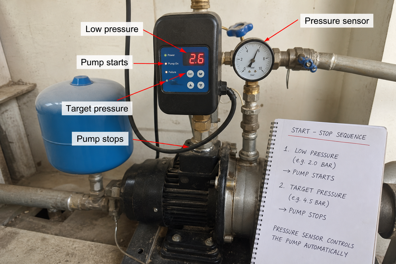
Field-style article image prepared for how does a booster pump work.
A booster pump works by sensing a pressure drop, starting the pump or increasing speed, and adding energy to the water until the system reaches its pressure target. The controller may read pressure at the pump discharge, a downstream header, or a remote sensor. That sensor location matters because the pump can only correct the pressure it is actually measuring.
A booster pump works by sensing downstream pressure, comparing that reading to a programmed setpoint, and adjusting motor speed or staging additional pumps to maintain the target. The control loop runs continuously: a pressure transducer at the discharge or at a remote point feeds real-time data to the controller, which modulates pump output to correct any deviation. When demand rises and pressure drops, the controller increases speed or starts a lag pump. When demand falls and pressure climbs, the system reduces speed or stops a pump to prevent overpressure.
Key Takeaways
- Booster pumps rely on closed-loop pressure feedback; the transducer location determines what the system actually controls.
- Variable-frequency drives adjust motor speed in real time, while constant-speed systems cycle pumps on and off based on pressure switches.
- Setpoint configuration must account for elevation head, friction loss, and the minimum fixture pressure required by code.
- Staging logic in multi-pump systems prevents short-cycling and balances runtime across all units.
Pressure Sensing and Transducer Placement
The pressure transducer converts mechanical pressure into an electrical signal the controller can read. Most industrial booster systems use a 4-20 mA analog signal or a digital protocol such as Modbus. The transducer mounts either at the pump discharge header or at a representative point in the distribution system.
Discharge-mounted transducers read the pressure leaving the pump station. This location works when the distribution system is short and friction loss is predictable. The controller holds discharge pressure constant, and the system designer must ensure that setpoint accounts for pipe loss and elevation to the farthest or highest fixture.
Remote-mounted transducers measure pressure at a critical use point, such as the highest floor or the end of a long pipe run. This configuration controls delivered pressure directly, compensating for friction and elevation automatically. Installation cost rises because the transducer requires wiring or a wireless link back to the pump controller, but the system maintains tighter pressure regulation under varying flow conditions.
Control Modes and Motor Modulation
Variable-frequency drive systems adjust pump speed continuously. The controller reads the pressure signal, calculates the error between actual and setpoint, and sends a speed command to the VFD. A proportional-integral-derivative algorithm smooths the response to prevent hunting or overshoot.
As flow demand increases, pressure begins to drop. The controller detects the drop and ramps motor speed higher, shifting the pump operating point up its curve. The system reaches equilibrium when the pump delivers enough flow at the required head to match demand and hold setpoint pressure.
Constant-speed systems use pressure switches instead of transducers and modulating drives. A lead pump starts when pressure falls below the cut-in setpoint and stops when pressure rises above the cut-out setpoint. The deadband between cut-in and cut-out prevents rapid cycling. If one pump cannot maintain pressure, a second pump starts at a lower cut-in threshold.
Staging Logic in Multi-Pump Systems
Multi-pump booster stations use staging controllers to balance wear and prevent one pump from carrying the entire load. The controller designates one pump as lead and the others as lag. When the lead pump reaches a configured speed threshold—typically 85-95% of maximum—and pressure still trends downward, the controller starts a lag pump.
Both pumps then share the load. The controller may reduce lead-pump speed slightly to prevent overpressure when the second pump comes online. If demand continues to rise, a third pump stages in using the same logic.
Lead-lag rotation ensures even runtime. After each off cycle, the controller advances to the next pump in sequence. If pump 1 was lead during the last call, pump 2 becomes lead for the next call, and pump 1 moves to first-lag position. This rotation distributes mechanical wear and prevents one unit from accumulating disproportionate hours.
Staging delays prevent nuisance starts during brief demand spikes. A typical delay holds the lag-pump start for 5-15 seconds after the speed or pressure threshold triggers. If pressure recovers during the delay, the lag pump does not start.
Setpoint Configuration and System Head Calculation
The controller setpoint must equal the sum of required fixture pressure, elevation head, and friction loss. Each component comes from design standards or hydraulic calculation.
Minimum fixture pressure is set by plumbing code, typically 15-20 psi for most applications and higher for specific equipment. Elevation head equals 0.433 psi per foot of vertical rise from the pump discharge to the highest fixture. Friction loss depends on pipe size, length, fitting count, and flow rate; the designer calculates this using the Hazen-Williams or Darcy-Weisbach equation.
**Example calculation:**
Highest fixture: 45 ft above pump discharge
Required fixture pressure: 20 psi
Friction loss at design flow: 12 psi
Elevation head = 45 ft × 0.433 psi/ft = 19.5 psi
Total setpoint = 20 + 19.5 + 12 = 51.5 psi, rounded to 52 psi
If the transducer mounts at the pump discharge, the controller setpoint is 52 psi. If the transducer mounts at the highest fixture, the setpoint is 20 psi, because elevation and friction losses occur between the pump and the sensor.
System Response to Flow Changes
When a valve opens or additional fixtures begin drawing water, flow increases and pressure drops. The pressure drop propagates back through the piping to the transducer. The controller sees the pressure signal fall below setpoint and increases the speed command to the VFD.
The motor accelerates, moving the pump operating point to a higher flow and higher head on its performance curve. Discharge flow rises until it matches the new demand, and pressure stabilizes at the setpoint. The entire response typically completes in 2-5 seconds for a well-tuned system.
When demand decreases, pressure rises because the pump continues to deliver flow into a system that now requires less. The controller reduces motor speed, and the operating point shifts down the curve. If demand drops to zero, the pump reaches minimum speed and pressure continues to rise. Most controllers stop the pump entirely or idle at low speed with a bypass valve to prevent deadheading.
Common Control Issues and Diagnostic Steps
Pressure cycling indicates incorrect deadband, staging delay, or PID tuning. If pressure swings 5-10 psi above and below setpoint, the controller is overcorrecting. Widening the proportional band or increasing the integral time constant smooths the response.
Failure to maintain setpoint under load suggests the pump is operating beyond its curve, friction loss exceeds the design estimate, or a downstream restriction has developed. Check the pump curve at the current flow and verify the system delivers the expected total dynamic head. If the pump runs at maximum speed and pressure remains low, the unit is undersized or the system demand increased since installation.
Remote transducer signal loss causes the controller to interpret zero or maximum pressure, triggering a fault or runaway condition. Most controllers include a sensor-fault detection algorithm that stops the pump if the signal leaves the expected 4-20 mA range for more than a few seconds. Field diagnostics require verifying transducer power, checking loop resistance, and confirming signal continuity at the controller terminals.
Commissioning and Initial Setup
Commission the booster system by verifying transducer calibration before energizing pumps. Apply a known pressure using a calibrated gauge and confirm the controller displays the same value within ±1 psi. Incorrect calibration shifts the entire control loop and causes persistent setpoint errors.
Set the controller to manual mode and ramp each pump from minimum to maximum speed while monitoring discharge pressure and motor current. Verify the pump reaches design head at design flow and that current remains below nameplate rating. If current exceeds the limit, check for incorrect impeller diameter or overspeed configuration.
Return to automatic mode and simulate demand changes by opening and closing isolation valves downstream of the transducer. Confirm the controller responds within 5 seconds, holds setpoint within ±3 psi during steady flow, and stages lag pumps at the configured threshold. Adjust PID parameters or staging delays if the system hunts or cycles excessively.
Record the final setpoint, staging thresholds, transducer location, and PID parameters in the operation and maintenance manual. Future troubleshooting depends on comparing field behavior to the commissioned baseline.
FAQs
What happens if the pressure transducer fails?
Most controllers enter a fault state and stop all pumps to prevent uncontrolled operation. Some systems include redundant transducers and switch to the backup signal automatically. Field replacement requires draining the transducer port, removing the failed unit, installing a new transducer with pipe sealant or a sealing washer, repressurizing the system, and recalibrating the controller.
Can a booster pump system run without a pressure tank?
Yes, if the pump uses a variable-frequency drive. The VFD modulates speed to match demand and eliminate the pressure fluctuations a tank would otherwise absorb. Constant-speed systems require a tank to reduce start-stop cycling and provide short-term storage during the time lag between pressure drop and pump start.
How does altitude affect setpoint configuration?
Altitude reduces atmospheric pressure but does not change the pressure required to lift water or overcome friction. The setpoint calculation remains identical. However, altitude affects net positive suction head available, which influences suction-side design and pump selection, not the discharge setpoint.
Conclusion
Booster pump operation centers on the control loop: the pressure transducer provides real-time feedback, the controller compares that signal to a configured setpoint, and the motor modulation or staging logic adjusts output to eliminate the error. Successful commissioning requires verifying transducer calibration, confirming setpoint calculation accounts for elevation and friction, and tuning the controller response to prevent cycling while maintaining tight pressure regulation. Field diagnostics begin with comparing observed pressure and speed to the expected operating point on the pump curve, then checking signal integrity if the controller behavior does not match system conditions.