
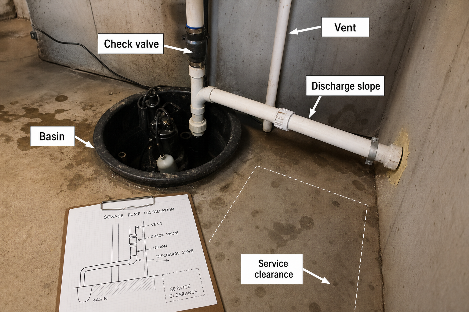
Field-style article image prepared for sewage pump installation diagrams.
A sewage pump installation diagram maps the physical arrangement of the pump, basin, discharge piping, valves, venting, and controls in a wastewater transfer or lift station. The diagram defines vertical clearances, horizontal pipe runs, check valve location, basin volume, and vent termination to ensure reliable solids handling, prevent backflow, and meet plumbing codes.
Most residential and light commercial sewage systems use submersible sewage pumps inside prefabricated basins with 18- to 30-inch diameters. The pump sits on a base or guide rail system 2 to 6 inches above the basin floor to allow settled grit to accumulate below the impeller intake. Discharge piping rises vertically inside the basin, exits through a sealed penetration, and connects to a horizontal run with a gate valve, union, and check valve in series before joining the gravity drain or pressure main.
Key Takeaways
- Basin diameter must exceed pump body width by 6 inches minimum; depth provides 12 to 18 inches of storage between pump-on and pump-off levels.
- Check valves install in the horizontal discharge run after the union, never in vertical pipe where solids settle and jam the flapper.
- Vent pipe diameter equals or exceeds discharge pipe diameter and terminates outdoors above the roofline or 10 feet from openings.
- Discharge pipe velocity should remain between 2 and 8 ft/s at design flow to keep solids in suspension without excessive friction loss.
Basin Layout and Pump Placement
The basin provides wet well volume, pump support, and access for maintenance. Residential sewage basins typically range from 18 to 24 inches in diameter and 24 to 36 inches in depth, fabricated from high-density polyethylene or fiberglass.
Pump placement follows two common methods. In a simplex system with one pump, the unit rests on the basin floor or on a short pedestal that raises the inlet screen 2 to 4 inches above settled debris. Duplex systems with two pumps use a guide rail assembly that suspends each pump from a discharge elbow and allows vertical removal without entering the basin.
Basin volume between the low-level (pump-off) and high-level (pump-on) float switches defines the pump cycle time. The formula is:
**V = Q × t / 4**
Where:
- V = basin storage volume, gallons
- Q = pump flow rate at system head, gpm
- t = minimum acceptable cycle time, minutes (typically 1 to 2 minutes)
- Factor 4 accounts for 50% duty cycle (pump runs half the time)
A basin storing 15 gallons between float levels and serving a 40 gpm pump will cycle every 1.5 minutes under continuous inflow. If cycle time falls below 1 minute, the pump may overheat or the control relay may fail prematurely. Increase basin diameter or adjust float spacing to extend cycle time.
Check Valve and Union Placement
The check valve prevents reverse flow when the pump stops, keeping the discharge line charged and preventing backflow into the basin. Check valve selection depends on solids content and system pressure.
Spring-loaded swing check valves handle sewage with solids up to 3 inches and operate in horizontal or vertical-up pipe. Silent check valves use a spring-assisted disc and close faster than gravity swing checks, reducing water hammer in systems with long vertical discharge runs. Ball check valves suit slurries but add higher head loss.
Install the check valve in the horizontal discharge run, 12 to 24 inches downstream of the basin penetration. Placing a check valve in vertical pipe allows solids to settle on the seat, preventing full closure and causing backflow. The union installs between the pump discharge elbow and the check valve, allowing pump removal without cutting pipe.
Vent Pipe Sizing and Termination
Basin venting prevents vacuum formation during pump discharge and allows sewer gases to escape safely outdoors. Without proper venting, the pump must work against negative pressure, reducing flow and increasing motor load. Methane and hydrogen sulfide can also accumulate inside sealed basins, creating explosion and odor hazards.
Vent pipe diameter must equal or exceed the discharge pipe diameter. A 2-inch discharge line requires a 2-inch or larger vent. The vent penetrates the basin lid or sidewall above the high-water alarm level and runs continuously upward without traps or dips that could collect condensate.
Termination follows local plumbing codes. Most jurisdictions require the vent to extend through the building roof and terminate at least 6 inches above the roofline, or 10 feet horizontally from any window, door, or air intake. Some codes allow termination outdoors at grade if the vent includes a 180-degree return bend and insect screen, but roof termination is preferred for odor control.
Discharge Pipe Configuration and Slope
The discharge line connects the pump to the gravity sewer main or pressurized force main. Piping layout affects solids transport, friction loss, and system reliability.
Vertical pipe inside the basin should be rigid Schedule 40 PVC or equivalent, supported at the basin penetration. The pipe rises to the basin lid or sidewalk level, then transitions to horizontal with a long-sweep 90-degree elbow. Avoid standard 90-degree elbows; the sharp turn increases head loss and can trap solids.
Horizontal discharge pipe should slope upward at 1/8 to 1/4 inch per foot toward the destination. Downward slopes create air pockets at high points that reduce flow and increase pressure surge during startup. If a downward slope is unavoidable, install an automatic air release valve at the peak.
Velocity in the discharge line must keep solids in suspension. The minimum velocity is 2 ft/s; below this threshold, solids settle in horizontal runs. Maximum velocity is typically 8 ft/s to limit friction loss and water hammer. Calculate velocity as:
**v = 0.408 × Q / d²**
Where:
- v = velocity, ft/s
- Q = flow rate, gpm
- d = inside pipe diameter, inches
For a 50 gpm pump on a 2-inch Schedule 40 PVC pipe (2.067-inch ID), velocity is 0.408 × 50 / 2.067² = 4.8 ft/s, which is acceptable.
Gate Valve and Isolation
A gate valve installs in the horizontal discharge run between the check valve and the building drain connection. This valve allows isolation for check valve service or pump removal without draining the entire discharge line.
Position the gate valve within reach from grade or access level. In outdoor installations, place the valve in a valve box with a removable cover. The valve should be a resilient-wedge or knife-gate design rated for sewage service; standard brass gate valves corrode rapidly in wastewater.
Never close the gate valve while the pump is running. Deadheading a sewage pump causes immediate motor overload and can rupture the pump volute or pipe fittings. Install a pressure gauge or pressure switch downstream of the gate valve to verify the valve is open before pump startup.
Component Inspection Checklist
Before commissioning a sewage pump installation, verify each element against the diagram:
Component | Requirement | Check |
Basin diameter | Pump body + 6 in minimum | ☐ |
Pump clearance | 2–6 in above floor | ☐ |
Check valve orientation | Horizontal run, arrow toward discharge | ☐ |
Union location | Between pump and check valve | ☐ |
Vent diameter | Equal to or larger than discharge pipe | ☐ |
Vent termination | Above roofline or 10 ft from openings | ☐ |
Discharge slope | 1/8 to 1/4 in/ft upward | ☐ |
Gate valve access | Reachable from grade or platform | ☐ |
Float spacing | Provides 1–2 min cycle time at design flow | ☐ |
High-water alarm | 3–6 in above pump-on level | ☐ |
Each item affects system performance or code compliance. Missed clearances cause installation failure during inspection or pump binding during operation.
FAQs
Can I install the check valve vertically if space is limited?
No. Solids settle on the valve seat in vertical installations, preventing full closure and causing backflow into the basin. If horizontal space is restricted, use a compact spring-loaded check valve or a combination check valve with an integral air release, but maintain horizontal orientation.
What happens if the vent pipe is undersized?
The pump must overcome negative pressure inside the basin, reducing flow by 5 to 15 percent and increasing motor current. Sewer gases may also leak through the basin lid seal or pump cable penetration, creating odor complaints. Upsize the vent to match the discharge pipe diameter.
How do I calculate basin volume for duplex alternating pumps?
Use the same formula, but base cycle time on the flow rate of a single pump. The basin must store enough volume to prevent short cycling even when one pump handles the full load. Duplex systems often require 20 to 30 gallon storage volumes in residential applications.
Should I use a backwater valve instead of a check valve?
No. Backwater valves are designed for gravity drainage protection and may not close fast enough in a pressurized sewage discharge. Use a pump-rated check valve with a pressure rating that exceeds the pump shutoff head by at least 50 percent.
Conclusion
A complete sewage pump installation diagram defines basin geometry, pump placement, check valve location, vent routing, and discharge pipe slope. Verify that basin volume supports a 1- to 2-minute pump cycle, the check valve sits in a horizontal run, the vent diameter matches or exceeds the discharge diameter, and pipe velocity stays between 2 and 8 ft/s. Installations that deviate from these layouts often fail inspection or experience short pump life, backflow, or odor problems. Use the component checklist during pre-commissioning inspection to confirm each element matches the approved diagram and local code requirements.