
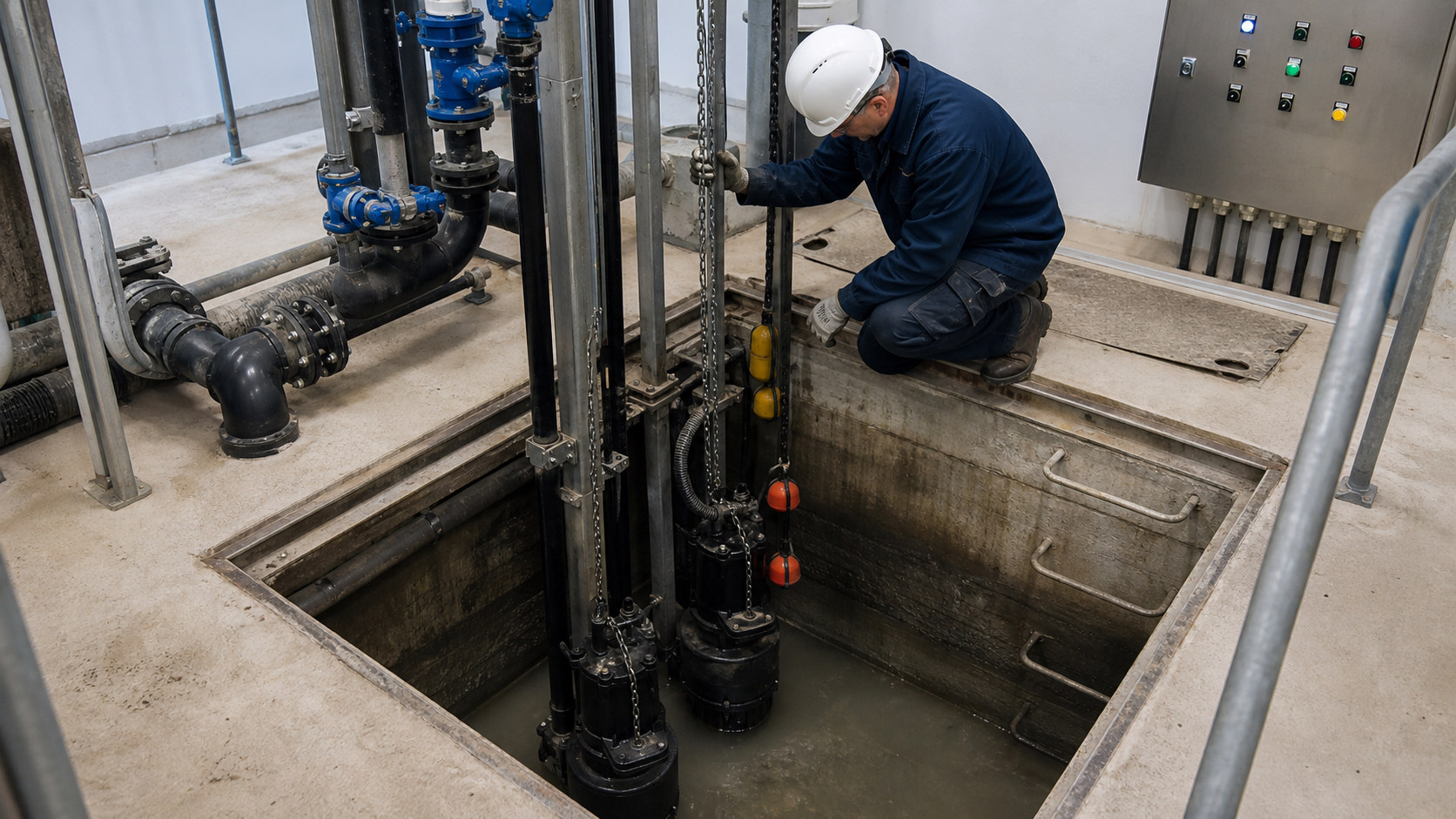
A sewage lift station alarm at 3 a.m. means either the basin level rose past the high-water switch or the control circuit lost power. The distinction matters because the first diagnosis requires checking float position, inlet flow, and pump discharge capacity, while the second demands electrical panel inspection, breaker status, and backup-power logic. Sewage pump maintenance separates mechanical evidence from electrical assumptions before opening the basin or pulling the pump.
Routine maintenance addresses solids passage, float-switch reliability, check-valve seating, basin accumulation, and alarm function. Unlike clean-water centrifugal pumps, sewage units handle rags, wipes, and grit that bind impellers, jam cutters, and foul mechanical seals. A scheduled inspection cycle catches developing problems before they trigger high-level alarms, protects hydraulic efficiency, and documents corrective work for regulatory and warranty purposes.
Key Takeaways
- Verify basin water level and float position before assuming electrical failure when a high-level alarm sounds.
- Inspect impeller passages, cutter assemblies, and inlet screens for rags, wipes, and grit accumulation according to manufacturer recommendations and observed duty cycle.
- Test check-valve seating and discharge isolation valves to prevent backflow into the basin between pump cycles.
- Document pump run time, cycle count, and amperage draw to identify wear patterns and confirm operation near best efficiency point.
- Replace mechanical seals and wear rings when leakage rate, bearing temperature, or vibration exceed manufacturer limits.
- Follow confined-space entry, electrical lockout, and pressure-release procedures before inspecting or servicing any sewage pump.
Make the Basin Safe before Inspection
Sewage basins qualify as confined spaces under OSHA 1910.146 when access requires entry through a manhole and the enclosure limits natural ventilation. Obtain an entry permit, test atmosphere for oxygen content and toxic gases, establish continuous forced ventilation, and post an attendant before descending into any wet well. Electrical isolation requires opening and tagging the motor disconnect, verifying zero voltage at the pump contactor, and discharging stored energy in capacitors or VFD bus capacitors.
For submersible sewage pumps, lower the basin level by pumping down to the low-level cutoff or transferring flow to a redundant pump before lifting the unit. Disconnect the pump power cable at the junction box above the basin and isolate the discharge valve to prevent backflow from the force main. For dry-pit installations, close the suction and discharge isolation valves, drain the volute through the bottom plug, and verify zero pressure before loosening mechanical-seal gland bolts or casing fasteners.
Sewage contact requires eye protection, chemical-resistant gloves, and protective clothing. Dispose of contaminated rags, seal washout water, and pump debris according to local wastewater regulations. Wash hands thoroughly after completing work.
Routine Checks for Level Controls, Alarms, and Duty Cycling
Float switches control pump start and stop levels in simplex and duplex sewage lift stations. A mechanical rod float or tethered ball float rises with the basin water level and closes a normally open contact at the pump-start elevation, then opens the contact at the pump-stop elevation. In duplex systems, a second float activates the lag pump if the lead pump fails or cannot keep pace with inlet flow, and a third high-level float triggers an alarm and may start both pumps simultaneously.
Test float operation by manually lifting each float to the actuation position and verifying that the control panel energizes the correct pump contactor. Testing frequency depends on jurisdiction requirements, manufacturer recommendations, and station criticality. Clean float hardware and pivot points to remove grease, rags, and calcium deposits that restrict motion. Replace floats that show cracked housings, waterlogged foam, or corroded switch mechanisms. Verify that float cable length positions the switch at the design water level by measuring from the basin floor or referencing the installation drawing.
Record pump cycle count and total run time from the hour meter or SCADA system. Frequent short cycles indicate undersized basin volume, check-valve leakage allowing backflow, or excessive inflow. Compare measured cycle behavior to the design alternation pattern documented in the station commissioning records. Continuous operation without reaching the stop level signals inadequate pump capacity, a fouled impeller, or a closed discharge valve. Investigate deviations from design behavior before they cascade into alarm conditions.
Pump, Inlet, Cutter or Impeller, and Solids Inspection
Lift submersible sewage pumps using the lifting chain or cable designed for the unit’s wet weight. Position the pump on a clean workbench and remove the suction cover or inlet screen. Inspect the impeller and cutter assembly for wrapped rags, plastic bags, and fibrous material. A vortex impeller or channel impeller passes solids by maintaining large internal passages, but rags still bind around the shaft or lodge between the impeller shroud and the casing wall.
For grinder sewage pumps, inspect cutter blades and the stationary cutter ring for wear, chips, or dull edges that reduce cutting efficiency. Blade-to-ring clearance increases as components wear; consult the manufacturer manual for replacement limits, which vary by model and duty. Excessive clearance allows uncut solids to pass into the volute and discharge piping, where they accumulate and restrict flow.
Remove impeller retaining hardware—a capscrew, locknut, or snap ring depending on pump design—and slide the impeller off the motor shaft. Measure wear-ring clearance between the impeller hub and the suction-cover insert using feeler gauges. Clearance growth reduces pump efficiency and lowers shutoff head. Replace wear rings when clearance exceeds the manufacturer limit or when measured flow at a fixed head drops below the acceptable range specified in the pump curve and installation manual.
Check Valve, Discharge Pipe, and Isolation Valve Checks
A swing check valve installed in the discharge piping prevents backflow when the pump stops, protecting the motor from reverse rotation and keeping the basin level from rising as water drains back through the impeller. Silent check valves or spring-assisted check valves close faster than plain swing checks and reduce water-hammer impact when the pump shuts off. In sewage service, check valves accumulate grit and rags that prevent full closure or jam the disc in a partially open position.
Test check-valve seating by listening for backflow after pump shutdown or by measuring basin water-level rise during the off cycle. A leaking check valve causes the water level to climb above the normal stop level within minutes of pump cutoff, triggering unnecessary restart cycles. Remove and disassemble the check valve body, clean the disc seat and hinge pin, and replace worn or corroded components. Vertical check valves require a longer riser above the pump discharge to allow the disc to swing fully open under flow; confirm that installation meets the minimum straight-pipe length specified in the valve manufacturer data.
Inspect discharge piping for cracks, corrosion, and joint leakage. Cast-iron and ductile-iron force mains develop graphitic corrosion or tuberculation that reduces effective pipe diameter and increases friction losses, forcing the pump to operate at higher head and lower flow than the design duty point. PVC and HDPE discharge lines resist corrosion but may sag between supports or separate at glued joints if installed without adequate bedding. Confirm that isolation valves open fully and close tightly; a partially closed discharge valve increases system head and shifts pump operation away from BEP, accelerating wear and raising power consumption.
Diagnose High Level, No Start, Short Cycling, and Low Flow
High basin level with pump running: Measure discharge pressure at the pump flange or force-main tap. Low pressure indicates a fouled impeller, reversed motor rotation, or broken impeller vanes. High pressure indicates a closed or restricted discharge valve, a plugged force main, or operation far to the left of BEP due to excessive system head. Shut down the pump, verify correct motor rotation direction by momentarily jogging the starter, and inspect the impeller and discharge path.
High level alarm with no pump start: Verify power at the motor disconnect and control-panel breaker. Check float-switch position manually and test electrical continuity from the float cable to the control relay. If power and float circuits are intact, measure motor winding resistance to detect open windings or ground faults. For submersible pumps, water intrusion through a failed mechanical seal often grounds the motor windings and trips the breaker or motor-protection relay.
Short cycling: Record the time between pump start and stop over several cycles. Cycles shorter than the design run time indicate undersized basin volume, a check valve leaking backflow into the basin, or float switches positioned too close together. One diagnostic approach calculates effective basin volume from measured cycle behavior:
V = Q × t_run
where V is the volume pumped per cycle in gallons, Q is average pump flow rate in gallons per minute, and t_run is measured run time in minutes. If this calculated volume is significantly less than the usable basin volume between start and stop levels, suspect check-valve leakage. If the calculated volume matches the expected basin volume but cycles remain shorter than design, reposition float switches to increase the start-stop band or reduce pump capacity by trimming the impeller or installing a VFD to lower operating speed.
Low flow or reduced discharge pressure: Compare measured discharge pressure to the pump curve at the expected flow rate. Pressure below the curve indicates impeller wear, increased wear-ring clearance, or internal recirculation. Shut down the pump and measure wear-ring clearance; if clearance exceeds manufacturer limits, replace the wear rings or the entire pump cartridge depending on the model. If wear rings are acceptable, inspect for air entrainment at the suction side, verify that the pump is fully submerged below the minimum submergence depth listed in the installation manual, and check the suction screen for blockage.
Electrical, Seal, Bearing, and Overheating Evidence
Measure motor amperage during steady-state operation and compare to the nameplate full-load current. Amperage significantly above nameplate indicates operation to the right of BEP—higher flow and lower head than design—or mechanical binding in the impeller or shaft. Amperage below nameplate suggests operation to the left of BEP, reduced impeller diameter, or worn impeller vanes that no longer generate rated head. If amperage matches nameplate but discharge pressure is low, suspect a worn impeller or incorrect motor speed; verify motor nameplate RPM and measure actual shaft speed with a tachometer.
Mechanical seals isolate the motor housing from the pumped liquid in submersible sewage pumps. Seal leakage allows wastewater to enter the oil-filled motor cavity, contaminating the lubricant and eventually grounding the motor windings. Inspect the seal chamber through the oil sight glass if equipped; cloudy or milky oil indicates water contamination. For double-seal designs, monitor the intermediate seal chamber pressure or liquid level; a drop signals failure of the inboard seal. Replace mechanical seals whenever oil contamination is detected or seal drip rate exceeds the manufacturer limit.
Bearing condition affects vibration amplitude and motor winding temperature. Measure vibration velocity in inches per second RMS or acceleration in g-peak at the pump mounting flange or motor housing. Acceptable vibration levels are model-specific; consult manufacturer guidance or recognized standards such as ISO 10816 for centrifugal pump vibration classification. Increasing vibration trends indicate bearing wear, impeller imbalance, or shaft misalignment. For dry-pit pumps, check bearing temperature with an infrared thermometer; bearing housing temperature significantly above ambient suggests inadequate lubrication, bearing wear, or excessive shaft load from misalignment.
Cleaning, Test Run, and Maintenance Record
After inspection and component replacement, flush the pump casing and impeller passages with clean water to remove residual grit and debris. Reinstall the pump in the basin, reconnect the power cable and discharge piping, and verify that all fasteners are torqued to specification. Open the discharge isolation valve fully and restore power at the motor disconnect. Manually activate the pump by lifting the start-level float and observe the discharge stream for steady flow without air pockets or pressure surges.
Measure and record discharge pressure, amperage, and run time during the test cycle. Compare pressure to the pump curve at the estimated flow rate; significant deviation signals incomplete impeller cleaning, incorrect reassembly, or system changes since the original installation. If pressure and amperage are within expected ranges, allow the basin to fill naturally and verify that the pump starts at the correct water level, runs until the stop level is reached, and shuts off cleanly without excessive water hammer.
Document the maintenance work in a station log or SCADA maintenance module. Record the date, technician name, components inspected, measurements taken, parts replaced, and any deviations from normal operation. Attach photos of worn impellers, failed seals, or corroded hardware to support future budget requests or warranty claims. Schedule the next inspection based on pump duty cycle, operating environment, manufacturer recommendations, and regulatory requirements.
FAQs
What causes a sewage pump to run continuously without shutting off?
Continuous operation indicates the pump cannot lower the basin level to the stop-float position. Common causes include inadequate pump capacity for the inlet flow rate, a fouled or worn impeller reducing output, a closed or restricted discharge valve increasing system head, or the stop float stuck in the down position. Measure discharge pressure and compare to the pump curve to isolate hydraulic problems from control failures.
How do I know when to replace the impeller instead of cleaning it?
Replace the impeller when vane thickness is reduced significantly from the original dimension due to abrasive wear, when cracks or chips are visible in the vane leading edges, or when measured pump performance drops substantially below the published curve after cleaning and wear-ring replacement. Consult the manufacturer service manual for model-specific replacement criteria. Minor surface roughness from grit erosion does not require impeller replacement if hydraulic performance remains acceptable.
Can I increase the time between maintenance visits by installing a larger pump?
Oversizing the pump reduces run time per cycle but increases the off-cycle duration, allowing solids to settle in the basin and potentially clogging the inlet screen or suction bell. Proper pump sizing maintains adequate flow velocity in the basin and discharge piping to keep solids in suspension. Extending maintenance intervals requires improving inlet screening, adding a grinder pump ahead of the lift station, or upgrading to a more robust impeller design rather than simply increasing pump capacity.
Why does the check valve slam shut and cause water hammer?
Swing check valves close under the force of reverse flow when the pump stops; in systems with long discharge piping or high static head, the reversal velocity can be high enough to slam the disc against the seat and generate pressure spikes. Install a spring-assisted or silent check valve with controlled closure, reduce pump shutoff speed by adding a VFD with soft-stop ramp, or add an air chamber or surge tank to the discharge piping near the pump to absorb pressure transients.
What inspection records do I need to keep for regulatory compliance?
Municipal wastewater agencies typically require records of pump run time, cycle count, power consumption, alarm events, and maintenance actions. Reporting frequency and required data elements vary by jurisdiction. Some agencies mandate periodic inspection reports documenting float operation, check-valve condition, basin accumulation depth, and structural integrity. Consult your discharge permit and local ordinances for specific recordkeeping requirements, and retain all records for the period specified in your permit.
Conclusion
Effective sewage pump maintenance verifies water-level evidence before electrical diagnosis, inspects solids-handling components on a scheduled cycle, and documents measured performance against the manufacturer curve. Begin each service visit by verifying safe basin entry, test float and alarm circuits before lifting the pump, and record discharge pressure, amperage, and wear-ring clearance to catch efficiency losses early. When troubleshooting high-level alarms or low flow, measure system head and compare to the pump curve to isolate mechanical wear from hydraulic restrictions. For application-specific inspection intervals, replacement-part specifications, or pump-curve verification, consult the manufacturer installation and service manual or request technical guidance tailored to your station configuration and duty cycle.