
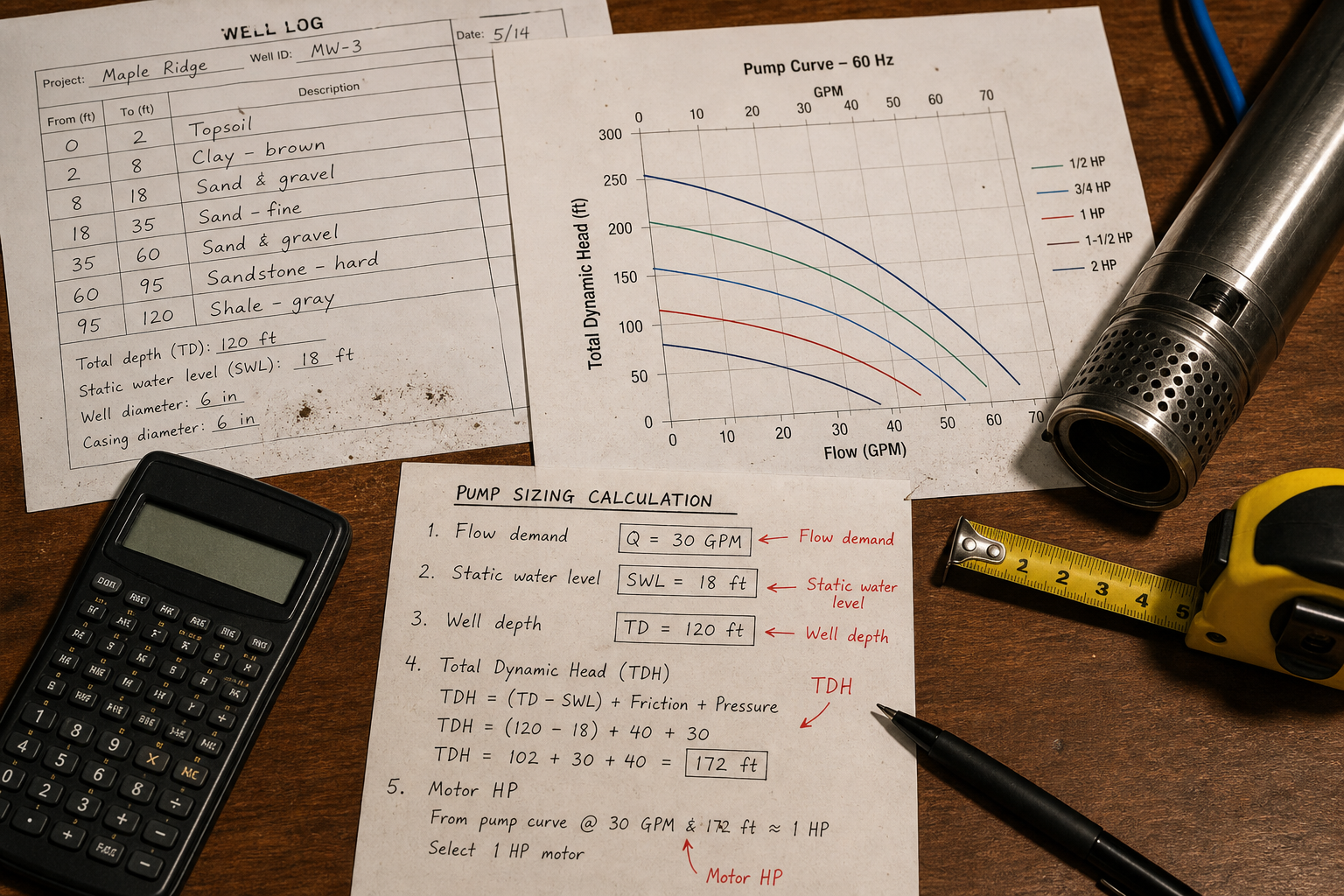
Field-style article image prepared for submersible well pump sizing calculator.
Submersible well pump sizing fails most often when the calculation stops at static water level. A useful sizing worksheet must include pumping water level, drawdown, column-pipe friction, required discharge pressure, motor cooling flow, and allowable starts per hour. Without those inputs, the selected pump may look correct on paper but operate outside the curve once the well is running.
Submersible well pump sizing requires four linked calculations: design flow rate in gallons per minute or cubic meters per hour, total dynamic head combining lift and friction losses, net positive suction head available at pump depth, and motor power accounting for efficiency and service factor. The calculator must use pumping water level—not static level—because drawdown during operation adds 20 to 150 feet of head depending on aquifer transmissivity and well construction.
Key Takeaways
- Total dynamic head equals pumping water level depth plus drawdown plus friction loss in column pipe plus surface discharge pressure
- Motor power in horsepower equals (flow in GPM × total head in feet) ÷ (3,960 × pump efficiency × motor efficiency), with service factor applied after
- Well yield from pumping tests sets the upper flow limit; sizing above yield causes progressive drawdown and eventual pump damage
- Column pipe friction varies with flow rate squared, so doubling flow increases friction loss by four times in the same pipe diameter
Flow Rate Determination From Demand Profile
Design flow rate comes from peak demand during the highest-use period, not instantaneous maximum. A residential well serving 15 homes may see 60 GPM peak aggregate demand, but if usage duration is 90 minutes twice daily, average demand is 12 GPM and continuous pump operation at 25 GPM meets the need with smaller motor and less thermal stress.
Duty cycle matters for motor selection even when flow rate is fixed. Pumps cycling more than six starts per hour need motors rated for frequent start duty, which adds 15 to 25 percent to power requirements compared to continuous-rated motors at the same horsepower.
Irrigation and industrial process wells should calculate flow from application rate and area. A 40-acre field with 0.25 inches per day requirement during peak season needs 452 GPM if irrigation runs 12 hours, or 226 GPM for 24-hour operation, before accounting for system efficiency losses.
Total Dynamic Head Calculation Structure
Total dynamic head (TDH) combines four components measured in feet of water column: pumping water level below surface, drawdown from static to pumping level, friction loss in column pipe and discharge line, and pressure head at final delivery point.
**Pumping water level** comes from drawdown test data at the design flow rate. Wells without test data require assumed drawdown, but this introduces 30 to 100 feet of uncertainty in formations with variable transmissivity. Static water level at 80 feet with 40 feet drawdown at 50 GPM gives 120 feet of lift before any friction loss.
**Column pipe friction** follows the Hazen-Williams equation: h<sub>f</sub> = 0.2083 × (100/C)<sup>1.852</sup> × (Q<sup>1.852</sup>/d<sup>4.87</sup>) × L, where h<sub>f</sub> is friction loss in feet, C is pipe roughness coefficient (typically 100-120 for steel, 130-140 for plastic), Q is flow in GPM, d is inside diameter in inches, and L is length in feet.
For a 300-foot column with 4-inch steel pipe (C=110) carrying 60 GPM: h<sub>f</sub> = 0.2083 × (100/110)<sup>1.852</sup> × (60<sup>1.852</sup>/4<sup>4.87</sup>) × 300 = 18.3 feet. Reducing to 3-inch pipe increases friction to 68 feet at the same flow, demonstrating the fourth-power diameter relationship.
**Surface pressure** converts from pounds per square inch to feet using the factor 2.31 feet per PSI. A system requiring 40 PSI at the pressure tank adds 92.4 feet to total head.
Well Depth and Drawdown Integration
Well depth sets the physical limit for pump placement, but operating head depends on pumping water level during flow. A 500-foot well with 100-foot static level and 150-foot pumping level at design flow requires calculating TDH from 150 feet, not 100 or 500.
Pump placement depth must keep the unit submerged below minimum pumping level by at least 25 feet for 4-inch pumps or 50 feet for 6-inch and larger units. Insufficient submergence causes cavitation when suction pressure drops below vapor pressure, collapsing bubbles that erode impeller surfaces and reduce flow by 10 to 40 percent before visible damage appears.
Seasonal water level variation requires using the lowest expected pumping level in the TDH calculation. Wells in areas with 40-foot seasonal decline must size pumps for the low-water condition even if this oversizes capacity during high-water months, because undersizing causes the pump to run continuously without meeting demand during critical periods.
Motor Power and Efficiency Factors
Motor horsepower calculation uses the water horsepower formula adjusted for pump and motor efficiency: HP = (Q × TDH) ÷ (3,960 × η<sub>pump</sub> × η<sub>motor</sub>), where Q is flow in GPM, TDH is in feet, and efficiencies are decimal fractions.
For 60 GPM at 250 feet TDH with pump efficiency 0.65 and motor efficiency 0.85: HP = (60 × 250) ÷ (3,960 × 0.65 × 0.85) = 6.84 HP. Select the next standard motor size—7.5 HP—rather than underrating with a 5 HP unit.
**Service factor** is a separate multiplier after base horsepower calculation. A 1.15 service factor motor can deliver 15 percent above nameplate rating for intermittent loads, but continuous operation at service factor reduces motor life by 40 to 60 percent compared to operation at rated power.
Three-phase motors in the 5 to 100 HP range typically show 85 to 92 percent efficiency, while single-phase motors run 70 to 82 percent efficient. The lower efficiency requires larger motors and increases operating cost by $150 to $400 annually per 10 HP at $0.12 per kWh with 4,000 hour duty.
Motor Size (HP) | Typical Efficiency | Service Factor | Voltage Options |
1-3 | 0.70-0.78 | 1.15-1.25 | 230V 1-phase |
5-10 | 0.82-0.87 | 1.15 | 230V/460V 3-phase |
15-50 | 0.88-0.91 | 1.10-1.15 | 460V 3-phase |
75-100 | 0.90-0.93 | 1.10 | 460V 3-phase |
Pump Curve Matching and Operating Point
The pump operating point sits at the intersection of system head curve and pump performance curve. System curve plots TDH against flow rate, increasing with the square of flow due to friction. Pump curve shows the manufacturer’s tested head-capacity relationship for a specific impeller diameter and speed.
Correct sizing places the operating point between 70 and 110 percent of best efficiency point (BEP) flow. Operation below 70 percent BEP increases radial thrust on bearings and creates recirculation zones that cause vibration and premature wear. Operation above 110 percent BEP overloads the motor and may exceed maximum recommended flow velocity in the column pipe.
When the calculated operating point falls outside this range, adjust either flow rate if demand allows flexibility, or change to a different pump model with BEP closer to the required duty point. Multi-stage pumps allow impeller quantity adjustment to match head while maintaining flow near BEP.
Cable Sizing and Voltage Drop Limits
Cable voltage drop from surface controller to submerged motor reduces available motor voltage and increases current draw. National Electrical Code recommends maximum 5 percent drop from service entrance to motor terminals, which translates to roughly 3 percent allowable drop in the well cable for typical installations.
Cable size calculation uses: VD = (2 × K × I × L) ÷ CM, where VD is voltage drop, K is 12.9 ohms per mil-foot for copper, I is full-load current in amperes, L is one-way cable length in feet, and CM is circular mil area. Rearranging for minimum cable size: CM = (2 × K × I × L) ÷ VD<sub>allowed</sub>.
A 10 HP motor at 460V three-phase draws approximately 14 amperes. At 350 feet depth with 3 percent allowable drop (13.8V): CM = (2 × 12.9 × 14 × 350) ÷ 13.8 = 9,049 circular mils. This requires #10 AWG minimum (10,380 CM), though #8 AWG (16,510 CM) provides margin for voltage sag during starting.
Selection Verification Checklist
After completing calculations, verify five conditions before finalizing pump selection:
- **Well yield test**: Confirm the aquifer sustained design flow rate for at least two hours without progressive water level decline beyond the assumed drawdown value
- **Minimum submergence**: Pump setting depth keeps all intake ports at least 25-50 feet below minimum pumping level during worst-case drawdown
- **Pipe velocity**: Flow velocity in column pipe stays below 5 feet per second for steel pipe or 8 feet per second for plastic to prevent erosion and water hammer
- **Motor cooling**: Flow past motor housing exceeds 0.5 feet per second for 4-inch pumps or 1.0 feet per second for 6-inch units to provide adequate cooling
- **Starting current**: Cable and starter are rated for locked-rotor current, typically 6 to 8 times full-load current for 5-50 HP motors
FAQs
What happens if I size the pump based on static water level instead of pumping level?
The pump will be undersized by the amount of drawdown, typically 20 to 150 feet. This causes the motor to run continuously without meeting demand, overheats the motor due to insufficient cooling flow past the housing, and may trip thermal overload protection during high-demand periods.
How do I account for future water level decline in the sizing calculation?
Use the lowest projected pumping level over the pump’s expected 15-20 year service life. Wells in declining aquifers should add 50-100 feet to current pumping level, or size the initial pump conservatively and plan for replacement when water level drops below economic pumping depth.
Can I use a larger motor than calculated to provide safety margin?
Motor oversizing by one standard frame size is acceptable, but oversizing by two or more sizes increases starting current demand, requires larger cable and starter, and may operate inefficiently at part load. The service factor provides adequate margin without oversizing the base motor rating.
Does column pipe material affect the sizing calculation?
Yes, through the Hazen-Williams C coefficient. Steel pipe (C=100-110) has higher friction than PVC or HDPE (C=130-140), requiring 8-15 percent more pump head at the same flow and diameter. Corrosion reduces C over time in steel, so use conservative values for long-term installations.
Conclusion
Submersible well pump sizing requires sequential calculation through flow rate, pumping water level with drawdown, friction losses in the full discharge path, and motor power with realistic efficiency values. The calculation fails when static water level replaces pumping level, when drawdown estimates lack test data, or when the system curve intersects the pump curve outside the 70-110 percent BEP operating range. Verify the final selection against well yield test results and minimum submergence requirements before procurement, and size cable for actual voltage drop rather than using rule-of-thumb wire gauge recommendations.