
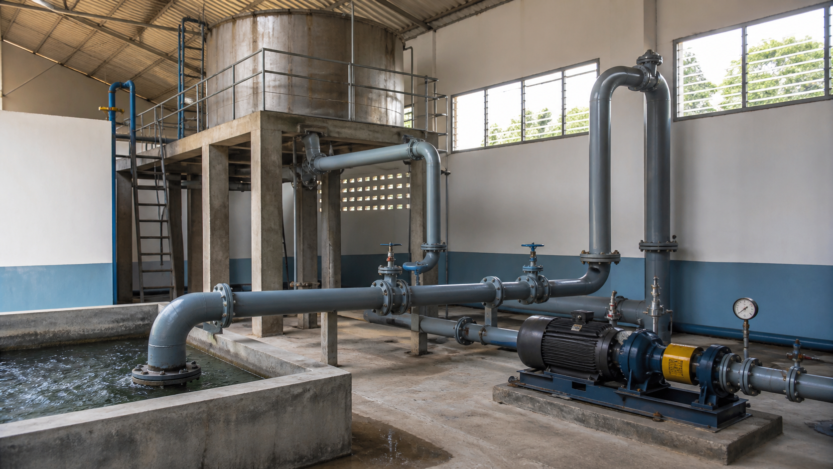
A pump rated for 20 feet of head will not transfer water between two tanks separated by 50 feet of elevation, no matter how close together they sit horizontally. The pump must overcome the vertical lift, friction in every pipe and fitting, and any pressure difference between the vessels. That combined energy requirement, expressed as equivalent height of liquid column, is the total dynamic head.
Total dynamic head calculation converts pressure loss, elevation change, and velocity change into a single number you can match to a pump performance curve. This guide defines each term, shows the complete formula with correct units, and walks through a worked example for open and closed systems.
Key Takeaways
- Total dynamic head (TDH) is static head plus friction losses plus pressure-head differences, all expressed in feet or meters of liquid column.
- Static head is the vertical elevation change from suction liquid surface to discharge liquid surface, measured at the pump’s defined reference points.
- Friction head includes losses in straight pipe, fittings, valves, heat exchangers, and any other component that resists flow.
- Velocity head is usually negligible in industrial water systems but must be added when suction and discharge pipe sizes differ significantly.
- The calculated TDH becomes the vertical axis coordinate on the pump curve; match it to your flow rate to find the duty point.
What Total Dynamic Head Includes
Total dynamic head sums four energy components, each converted to equivalent feet or meters of liquid:
- Static head: vertical distance the pump lifts the liquid, measured from suction liquid surface to discharge liquid surface.
- Friction head: energy lost to pipe wall friction, turbulence in fittings and valves, and resistance in filters, heat exchangers, or other equipment.
- Pressure head: difference between discharge pressure and suction pressure, expressed as head. Pressurized discharge vessels or vacuum suction tanks contribute to this term.
- Velocity head: kinetic energy difference between suction and discharge velocities. In industrial water systems with similar pipe sizes, this term is typically less than one foot.
Every term must be in the same unit—feet of water column or meters of water column—before you add them. Mixing pressure in psi with head in feet produces incorrect results.
Define the Suction and Discharge Reference Points
Static head depends on your measurement datum. For open suction and discharge tanks, measure the vertical distance from suction liquid surface to discharge liquid surface. Suction tank above the pump contributes negative static head; discharge tank above the pump contributes positive static head.
For closed systems—cooling loops, boiler feed circuits—there is no liquid surface. Static head is zero because the liquid returns to the same elevation. TDH in a closed loop equals friction head plus any pressure difference imposed by external equipment.
For well pumps, the suction reference is the pumping water level during operation, not the static water level before startup. The discharge reference is the elevation where water leaves the system—typically a storage tank surface or open discharge point.
Use the same datum for suction and discharge measurements. Measuring suction from ground level and discharge from pump centerline produces an error equal to the difference in reference planes.
Static Head, Pressure Head, Velocity Head, and Friction Loss
Static head is vertical geometry. Discharge surface 80 feet above suction surface gives 80 feet of static head. A pump drawing from an open sump at grade and discharging to a tank 30 feet above grade has 30 feet of static head. Flooded suction 10 feet below the pump centerline reduces total lift but does not change the static head calculation method—you still measure to the discharge surface.
Pressure head converts gauge pressure to equivalent liquid column:
h_p = (P × 144) / (ρ × g) in USCS units, or h_p = P / (ρ × g) in SI units.
For water at 60°F with density 62.4 lb/ft³, 1 psi equals 2.31 feet of head. Discharging into a vessel at 50 psig while drawing from a vented tank at 0 psig gives pressure head of 50 × 2.31 = 115.5 feet. Drawing from a vacuum tank at -5 psig increases the pressure difference to 55 psi and pressure head to 127 feet.
Velocity head is v² / (2g). For water in 4-inch schedule 40 pipe (inside diameter 4.026 inches, area 0.0884 ft²) flowing at 300 gpm (0.668 ft³/s), velocity is 7.56 ft/s and velocity head is 7.56² / (2 × 32.2) = 0.89 feet. Equal suction and discharge pipe sizes produce canceling velocity heads. Different sizes require calculating both and subtracting suction velocity head from discharge velocity head.
Friction head sums losses in every pipe segment, elbow, tee, valve, and equipment item. Use the Darcy-Weisbach equation or Hazen-Williams formula for straight pipe, then add equivalent length or K-factors for fittings. Manufacturer engineering guides provide friction tables or software. For initial estimates in typical industrial water service with velocities between 5 and 10 ft/s, assume 5 to 10 feet of friction loss per 100 feet of pipe, then add 50 to 100 percent for fittings and valves. Precise calculations require evaluating every component.
TDH Formula and Unit Discipline
The complete formula is:
TDH = h_static + h_friction + h_pressure + h_velocity
Where:
- h_static = elevation of discharge liquid surface minus elevation of suction liquid surface (feet or meters)
- h_friction = sum of all pipe, fitting, valve, and equipment losses (feet or meters)
- h_pressure = (P_discharge – P_suction) × conversion factor (feet or meters)
- h_velocity = (v_discharge² – v_suction²) / (2g) (feet or meters)
Unit conversion factors:
- USCS: 1 psi = 2.31 feet of water at 60°F (density 62.4 lb/ft³)
- SI: 1 bar = 10.2 meters of water at 20°C (density 998 kg/m³)
For liquids other than water, adjust the pressure-to-head conversion by specific gravity. Pumping a chemical with specific gravity 1.2 changes the conversion: 1 psi = 2.31 / 1.2 = 1.93 feet of chemical column.
Do not add feet and psi directly. Do not assume 1 psi equals 2.31 feet for hot water, glycol solutions, or hydrocarbons without checking density. Do not use pump centerline as elevation datum unless both suction and discharge measurements reference that same centerline.
Worked Water-Transfer Example
System: Transfer 400 gpm of water from a ground-level storage tank (open to atmosphere) to a rooftop cooling tower basin 65 feet above grade. Suction line is 6-inch schedule 40 steel pipe, 20 feet long with one 90° elbow and one ball valve. Discharge line is 4-inch schedule 40 steel pipe, 80 feet long with three 90° elbows, one check valve, and one gate valve. Water temperature is 70°F, density 62.3 lb/ft³.
Step 1: Static head
Discharge surface elevation: 65 feet above grade
Suction surface elevation: 0 feet (grade)
h_static = 65 – 0 = 65 feet
Step 2: Pressure head
Both tanks vented to atmosphere: P_suction = P_discharge = 0 psig.
h_pressure = 0 feet
Step 3: Velocity head
400 gpm = 0.891 ft³/s
6-inch pipe inside area = 0.2006 ft², velocity = 0.891 / 0.2006 = 4.44 ft/s
4-inch pipe inside area = 0.0884 ft², velocity = 0.891 / 0.0884 = 10.08 ft/s
v_discharge² / (2g) = 10.08² / (2 × 32.2) = 1.58 feet
v_suction² / (2g) = 4.44² / (2 × 32.2) = 0.31 feet
h_velocity = 1.58 – 0.31 = 1.27 feet
Step 4: Friction head
Using Hazen-Williams with C = 120 for steel pipe and water at 70°F.
Suction line (6-inch, 20 feet): friction loss ≈ 0.1 feet per 100 feet at 4.44 ft/s → 0.02 feet
Suction fittings: one 90° elbow (K ≈ 0.3), one ball valve fully open (K ≈ 0.05)
Total K_suction = 0.35, loss = 0.35 × (4.44² / 64.4) = 0.11 feet
Discharge line (4-inch, 80 feet): friction loss ≈ 3.5 feet per 100 feet at 10 ft/s → 2.8 feet
Discharge fittings: three 90° elbows (K ≈ 0.3 each), one check valve (K ≈ 2.0), one gate valve fully open (K ≈ 0.15)
Total K_discharge = 0.9 + 2.0 + 0.15 = 3.05, loss = 3.05 × (10.08² / 64.4) = 4.81 feet
h_friction = 0.02 + 0.11 + 2.8 + 4.81 = 7.74 feet
Total dynamic head:
TDH = 65 + 0 + 1.27 + 7.74 = 74 feet
On the pump curve, find the intersection of 400 gpm and 74 feet of head. That point should fall near the best efficiency point. Points significantly right of BEP suggest a smaller impeller or different model. Points far left indicate the pump will run out on its curve and may overload the motor.
Closed Loops, Pressurized Vessels, and Changing Liquid Levels
In closed heating or cooling loops, static head is zero because supply and return occupy the same elevation. TDH equals friction head only. A heat exchanger with 15 psi pressure drop converts to head: 15 × 2.31 = 34.7 feet (for water), added to pipe friction.
Pumping into pressurized vessels—bladder accumulators, reactor vessels under nitrogen blanket—requires including vessel pressure as discharge pressure. A vessel at 80 psig with atmospheric suction gives h_pressure = 80 × 2.31 = 184.8 feet.
When liquid level changes during batch transfers, calculate TDH at worst case. A sump draining 10 feet during transfer increases static head by 10 feet at cycle end. Size the pump for highest TDH, occurring when suction level is lowest and discharge level is highest. Some systems require control valves or VFDs to throttle flow as TDH decreases, preventing the pump from running to shutoff head.
For systems with varying flow rates—cooling towers with multiple cells cycling on and off—calculate TDH at minimum and maximum flow. Confirm both points fall within the pump’s stable operating range. Operating below minimum continuous flow causes recirculation and premature wear.
Turn the TDH Result into a Pump-Curve Duty Point
Once you have TDH and flow rate, plot the duty point on the pump curve. The curve shows head on the vertical axis and flow on the horizontal. Each impeller diameter or speed produces a different curve. The best efficiency point (BEP) is where the pump converts shaft power to hydraulic power most efficiently.
Select a pump whose curve passes through or near your duty point, within 10 percent of BEP flow when possible. If your calculated point is 400 gpm at 74 feet and the pump curve shows 400 gpm at 72 feet, the pump will deliver slightly more than 400 gpm because system resistance is lower than the pump provides at that head. If system curve and pump curve intersect at 420 gpm and 70 feet, that becomes your actual operating point.
Do not select a pump whose shutoff head (zero flow) is less than your TDH. Do not select a pump whose maximum flow barely exceeds your requirement; margin for fouling, wear, and future capacity is necessary. Confirm that NPSHa exceeds NPSHr by the margin specified in the pump manual.
After installation, measure suction pressure, discharge pressure, and flow rate. Convert the pressure difference to head and compare to calculated TDH. Measured values significantly higher indicate a closed valve, clogged strainer, or friction calculation error. Significantly lower values suggest a leaking check valve, open bypass, or miscalculated static head.
FAQs
How do you calculate total dynamic head for a submersible pump in a well?
Measure the vertical distance from the pumping water level (not the static level) to the discharge point, add friction losses in the drop pipe and surface piping, and add surface system pressure if the pump discharges into a pressure tank. Pumping level is lower than static level and must be estimated from well yield curves or measured during operation. If the well draws down 20 feet at your design flow, use that deeper level as your suction reference.
Does total dynamic head change if I use a variable frequency drive?
TDH is a system property, not a pump property. Reducing pump speed with a VFD decreases flow and friction losses (which vary with the square of flow), shifting the system curve downward. The pump curve also shifts according to affinity laws. The new intersection of system curve and pump curve gives lower flow and lower head, but the calculation method remains unchanged. Recalculate friction head at the new flow rate to find the new duty point.
Can I calculate TDH in psi instead of feet?
You can express the result in psi by dividing head in feet by 2.31 for water, but pump curves are published in feet or meters of head. Converting to psi obscures liquid density effects and complicates matching your operating point to the curve. Calculate in feet or meters and convert to pressure only when specifying pressure switches or gauges.
What happens if I underestimate friction loss?
The pump delivers less flow than expected because the actual system curve is steeper than your calculated curve. The duty point shifts left on the pump curve, efficiency drops, and process requirements may not be met. Severe underestimates cause the pump to run far from BEP, producing vibration, noise, and accelerated wear. Include a safety margin—10 to 20 percent additional friction head—for fouling, aging pipe, and calculation uncertainty.
Do I add suction lift or subtract it from discharge head?
Suction lift is the vertical distance from pump centerline down to suction liquid surface when the pump sits above the liquid. It increases total pump work, so it adds to TDH. In the formula, static head is total elevation change from suction surface to discharge surface, which automatically includes suction lift as a positive contributor. Do not subtract suction lift; the sign is correct when you measure elevation change from bottom to top.
Conclusion
Total dynamic head calculation combines static elevation, friction losses, pressure differences, and velocity changes into a single head value defining your pump duty point. Measure suction and discharge reference elevations carefully, convert all pressures to head using correct liquid density, and sum friction losses for every pipe segment and fitting. The resulting TDH and required flow rate become coordinates on the pump performance curve. Verify that the selected pump operates near its best efficiency point at that duty and confirm adequate NPSH margin before finalizing the specification. For complex systems with multiple operating modes or non-Newtonian fluids, provide the pump manufacturer with your system drawing, fluid properties, and detailed flow and pressure data so they can confirm the calculation and recommend the appropriate pump model and materials.