
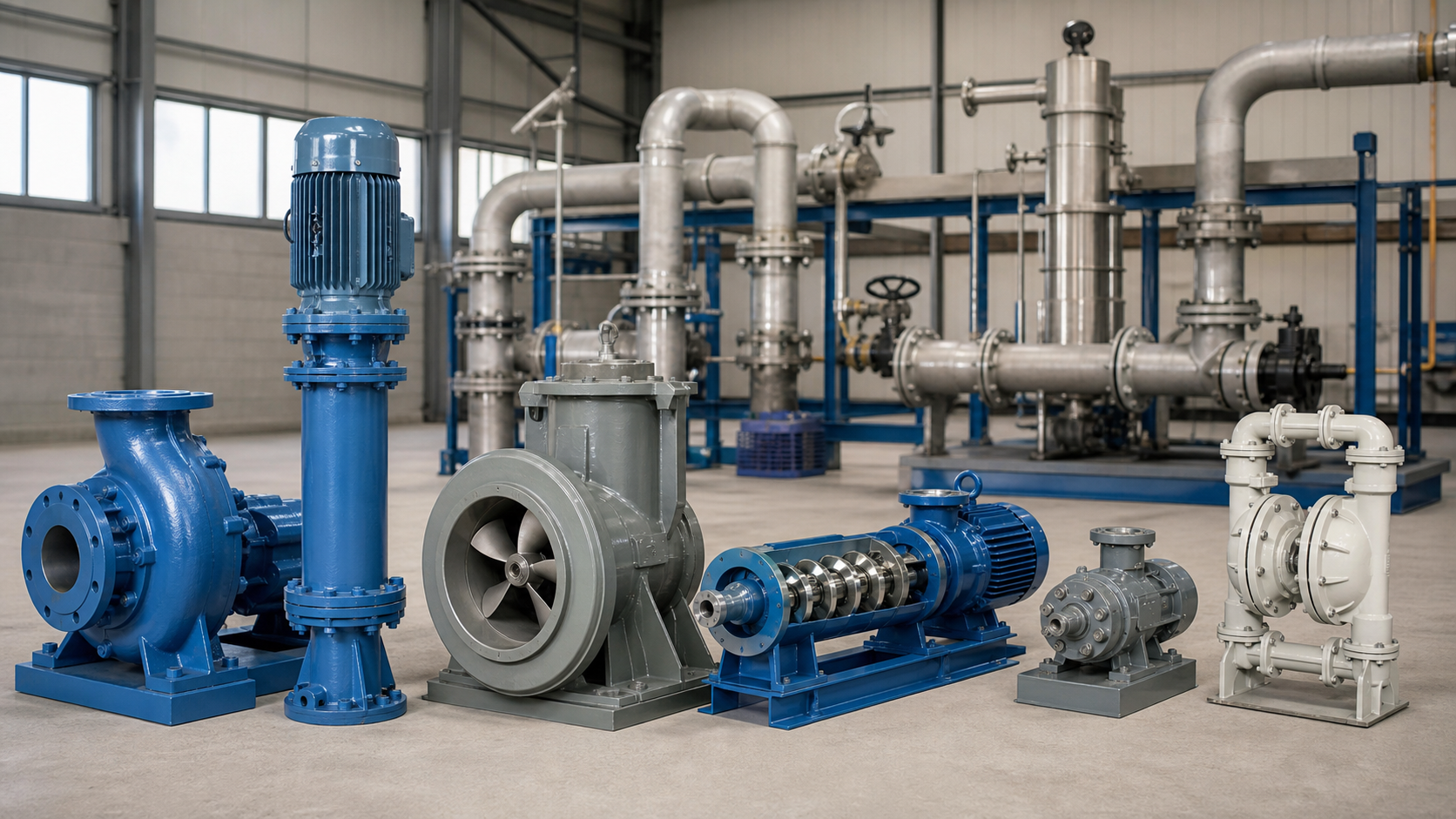
title: "Types of Industrial Pumps and Their Applications"
Selecting a pump begins with the system curve. Every fluid-handling system imposes a specific combination of flow rate and total dynamic head—the pressure required to overcome static lift, friction losses, and back-pressure at the design flow. Industrial pumps divide into two fundamental families: rotodynamic designs that transfer momentum to the fluid, and positive-displacement designs that trap and force fixed volumes through each cycle. The pump’s energy-addition mechanism and physical form must match the duty point, liquid properties, and site conditions.
Key Takeaways
- Energy-addition method divides all industrial pumps into rotodynamic (centrifugal, axial, mixed-flow) and positive-displacement (rotary, reciprocating) families; each responds differently to changes in system resistance.
- Centrifugal pumps deliver variable flow against variable head along a curve; positive-displacement pumps deliver nearly constant flow regardless of discharge pressure until relief protection activates.
- Viscosity, solids size, shear sensitivity, and vapor pressure determine whether a rotodynamic or positive-displacement design is appropriate before any subtype comparison.
- Sealless, submersible, and vertical configurations solve containment, installation, or NPSH problems without changing the underlying energy-transfer principle.
- A complete duty specification includes flow, head, liquid properties, temperature, solids, operating range, and installation drawing before requesting a pump curve or quotation.
First Divide Pumps by How They Add Energy
All industrial pumps increase fluid pressure by adding energy, but the mechanism differs between rotodynamic and positive-displacement designs. A rotodynamic pump accelerates the liquid with a rotating impeller or propeller, converting velocity into pressure as the fluid slows in the discharge passage. Flow rate varies with system resistance; if discharge pressure increases, flow decreases along the pump curve. A positive-displacement pump traps a fixed volume of liquid in a cavity and forces it into the discharge piping. Flow rate remains nearly constant across a wide pressure range, limited only by slip, compression, and relief-valve settings.
The duty point—the intersection of the system curve and the pump curve—must fall within the pump’s efficient operating range. For rotodynamic pumps, the manufacturer’s curve shows the acceptable flow window around the best efficiency point (BEP). Operating far from BEP increases radial thrust, recirculation, and vibration. Positive-displacement pumps tolerate a wider range but require relief protection because they generate unlimited pressure if the discharge is blocked.
Centrifugal, Axial-Flow, and Mixed-Flow Pumps
Centrifugal pumps use a rotating impeller to impart radial and tangential velocity to the liquid. The impeller may be closed (shrouded on both sides), semi-open (shrouded on one side), or open (no shrouds). Closed impellers deliver the highest efficiency and are standard for clean liquids. Semi-open and open impellers pass larger solids and resist clogging but sacrifice efficiency and require closer clearances to control internal recirculation. The casing converts velocity to pressure through a volute or diffuser. Single-stage pumps handle moderate heads; multistage pumps achieve higher heads by stacking impellers in series.
Centrifugal pumps suit applications with steady flow, moderate head, and low-viscosity liquids. Common industrial uses include cooling water circulation, chemical process transfer, and general utility service. They cannot self-prime unless fitted with a priming system or a foot valve. Available NPSHa must exceed required NPSHr by the margin specified in the pump curve to prevent cavitation.
Axial-flow pumps move liquid parallel to the shaft axis using a propeller-type impeller. They deliver very high flow at low head. The pump curve is steep; flow changes rapidly with small head variations. Axial pumps suit flood control, raw water intake, and large-volume cooling applications where head requirements are modest.
Mixed-flow pumps combine radial and axial velocity components. They handle higher flows than centrifugal pumps at intermediate heads. Mixed-flow pumps appear in municipal water supply, irrigation, and drainage where the duty point falls between centrifugal and axial territory.
Rotary Positive-Displacement Pumps
Rotary positive-displacement pumps trap liquid between moving and stationary elements, then force it toward the discharge. Flow is proportional to rotational speed and largely independent of discharge pressure, making them suitable for viscous liquids, batch metering, and shear-sensitive fluids. Common rotary pump types include gear pumps (external, internal, and lobe variants), screw pumps (single, twin, and triple screw), vane pumps, and progressive cavity pumps.
Gear pumps use meshing gears to carry liquid from suction to discharge in the spaces between teeth and casing. External gear pumps handle wide viscosity ranges and are common in lubrication, polymer transfer, and fuel handling. Internal gear pumps and lobe pumps offer gentler handling for food products and pharmaceuticals where shear damage must be minimized. Maximum pressure depends on construction; consult the manufacturer’s rating.
Screw pumps move liquid axially along intermeshing screws. Twin-screw and triple-screw designs deliver smooth, pulsation-free flow and handle two-phase mixtures with entrained gas or vapor. They suit crude oil transfer, fuel injection, and hydraulic systems requiring quiet operation and low shear. Progressive cavity pumps (single-screw) use an eccentric rotor inside an elastomeric stator, pumping abrasive slurries and viscous waste with minimal pulsation.
Vane pumps use sliding vanes in a rotor to form variable-volume chambers. They handle clean to moderately dirty liquids and operate at pressures defined by the casing and vane material. Vane pumps appear in fuel dispensing, solvent transfer, and bulk loading where a compact design and steady flow are required.
All rotary pumps require a relief valve on the discharge to prevent casing rupture if the outlet is blocked. Slip—internal leakage from discharge to suction—increases with pressure and decreases with viscosity. Low-viscosity liquids reduce volumetric efficiency; high-viscosity liquids increase power consumption and may require heating or dilution to maintain flow.
Reciprocating and Metering Pumps
Reciprocating pumps use a piston, plunger, or diaphragm moving in a cylinder to displace liquid. Flow is proportional to stroke length, speed, and the number of cylinders. Single-acting pumps displace liquid on one stroke direction; double-acting pumps displace on both. Pulsation is inherent; pulsation dampeners and multiple cylinders smooth the discharge.
Piston and plunger pumps deliver high pressures and handle moderate viscosities. They suit high-pressure washing, hydraulic testing, and oil-field injection. Plunger pumps seal at the packing; piston pumps seal at the piston rings inside the cylinder. Plunger designs allow higher pressure and easier maintenance but require clean liquid to avoid packing wear.
Diaphragm pumps use a flexible diaphragm actuated mechanically or hydraulically to displace liquid. The diaphragm isolates the liquid from the drive mechanism, preventing contamination and leakage. Diaphragm pumps handle corrosive, abrasive, and toxic fluids in chemical dosing, wastewater treatment, and mining. Hydraulically actuated diaphragm pumps achieve better accuracy and higher pressure than mechanically driven variants.
Metering pumps deliver precise, repeatable flow rates for chemical injection, pH control, and process dosing. They are typically diaphragm or plunger designs with adjustable stroke length or speed. Accuracy depends on construction, operating pressure, and liquid properties; refer to the manufacturer’s calibration data. Metering pumps require back-pressure to maintain prime and ensure check-valve seating; a discharge back-pressure valve or elevation head should be present.
Sealless, Submersible, Vertical, and Special Configurations
Some industrial services impose containment, installation, or suction constraints that require variations in mechanical layout or sealing strategy. These configurations do not change the underlying energy-addition mechanism but solve specific field problems.
Sealless pumps eliminate the shaft seal by containing the liquid entirely within a hermetic enclosure. Magnetic-drive pumps couple the motor to the impeller through a magnetic field across a containment shell. Canned-motor pumps enclose the rotor and bearings inside the pumped liquid, with the stator windings isolated by a thin can. Both designs prevent leakage of hazardous or toxic fluids and suit services where even minor seal drips are unacceptable. The trade-off is reduced efficiency, limited power, and sensitivity to dry running or abrasive wear on internal bearings.
Submersible pumps operate entirely submerged in the pumped liquid. The motor is sealed and cooled by the surrounding fluid. Submersible designs eliminate suction-lift limits and simplify installation in wet pits, wells, and sumps. They suit wastewater, mining dewatering, and water-supply applications where the pump must operate below grade. Motor cooling depends on adequate submergence; running dry causes overheating.
Vertical pumps mount with the motor above the liquid level and the impeller(s) submerged on a long shaft. Vertical turbine pumps deliver high heads from deep wells or tanks. Vertical inline pumps save floor space by eliminating a separate foundation and suction piping. Vertical sump pumps handle wastewater and slurries in open pits where horizontal mounting is impractical. Shaft alignment, bearing lubrication, and thrust load management are critical in long-shaft vertical designs.
Match Flow, Head, Viscosity, Solids, Shear, and Containment
Choosing the pump family requires matching six primary selection criteria to the application.
Flow and head define the duty point. High flow with low head favors axial or mixed-flow pumps. Moderate flow with moderate head suits centrifugal pumps. Low flow with high head or high discharge pressure requires multistage centrifugal or positive-displacement designs.
Viscosity shifts the boundary. Centrifugal pumps lose efficiency as viscosity increases; performance curves must be corrected using the manufacturer’s viscosity correction charts. Positive-displacement pumps handle high-viscosity liquids but require slower speeds and higher power input as viscosity increases.
Solids content and size determine impeller type and passage clearance. Centrifugal pumps with closed impellers pass small particles. Open impellers and large-passage designs pass larger solids. The manufacturer’s data sheet specifies maximum sphere diameter. Progressive cavity and diaphragm pumps handle slurries with high solids concentration. Solids cause abrasive wear; elastomer or ceramic liners extend life in slurry service.
Shear sensitivity matters for emulsions, polymers, and biological fluids. High-speed centrifugal pumps shear polymer chains and break emulsions. Positive-displacement designs with low tip speeds—lobe, progressive cavity, and peristaltic pumps—minimize shear damage.
Containment requirements drive seal and configuration choices. Toxic, flammable, or environmentally hazardous liquids require double mechanical seals, sealless designs, or leak-detection systems. Magnetic-drive and canned-motor pumps eliminate dynamic seals entirely.
Operating range affects pump curve shape. If the system operates at variable flow, the pump curve must maintain acceptable efficiency and NPSH margin across the entire range. Variable-frequency drives (VFDs) allow speed adjustment to match flow demand and reduce energy consumption.
Industrial Pump Application Selection Matrix
Application | Typical Flow | Typical Head | Liquid Type | Solids | Recommended Pump Family |
|---|---|---|---|---|---|
Cooling water circulation | High | Moderate | Clean water | None | Centrifugal (closed impeller) |
Boiler feed | Moderate | High | Treated water | None | Multistage centrifugal |
Chemical process transfer | Low to moderate | Moderate | Corrosive, varying viscosity | Trace | Centrifugal (semi-open) or gear |
Slurry pumping | Moderate to high | Low to moderate | Water + abrasive solids | Large | Centrifugal (open impeller, hard-faced) |
Viscous liquid transfer | Low to moderate | Moderate | High viscosity | None | Gear, screw, or progressive cavity |
Chemical metering | Very low | Moderate to high | Corrosive or hazardous | None | Diaphragm or plunger metering pump |
Raw water intake | Very high | Low | River or lake water | Debris | Axial-flow or mixed-flow |
Wastewater lift station | Moderate | Moderate | Sewage, organic solids | Large | Submersible centrifugal (non-clog) |
Dewatering | Moderate to high | Moderate | Groundwater, mine water | Sand, grit | Submersible centrifugal (abrasion-resistant) |
Hydraulic testing | Low | Very high | Clean water | None | Plunger pump |
This matrix provides general guidance. Verify the selection with the actual system curve, liquid properties, and site conditions. Manufacturer’s certified curves and performance corrections for viscosity, temperature, and specific gravity must be applied before finalizing the specification.
Data Required before Contacting a Pump Supplier
A complete pump specification prevents mismatched selections and reduces procurement time. Provide the following data:
- Flow rate at normal and maximum operating conditions.
- Total dynamic head or discharge pressure, including static lift, friction losses, and any back-pressure. If the system curve is available, provide the curve or friction coefficient and pipe dimensions.
- Liquid properties: density or specific gravity, viscosity at operating temperature, vapor pressure, temperature range, pH, and any corrosive or abrasive constituents.
- Solids content: particle size (maximum and typical), concentration by volume or weight, and abrasiveness.
- Suction conditions: available NPSHa or suction pressure, submergence or suction lift, and whether the pump must self-prime.
- Installation type: horizontal, vertical, submersible, or inline. Available floor space, foundation details, and motor location if constrained.
- Driver and control: electric motor voltage and frequency, explosion-proof classification if required, and whether a VFD will be used.
- Operating pattern: continuous duty, intermittent cycles, or variable flow. Minimum and maximum flow if the system operates over a range.
- Materials and seals: compatibility requirements for wetted parts, shaft seal type (mechanical seal, packing, or sealless), and any industry-specific approvals (API, ATEX, FDA, 3-A, etc.).
- Ambient and site conditions: elevation above sea level, ambient temperature, available utilities (cooling water, seal flush), and whether the pump will be installed indoors or outdoors.
Missing data forces assumptions. If discharge pressure is specified but total head is not calculated, the supplier must estimate friction losses. If liquid viscosity is unknown, the supplier will assume water properties, and the pump may be undersized. If solids content is omitted, a standard closed-impeller pump may be proposed and fail rapidly in slurry service. Accurate data ensures the supplied pump matches the actual operating conditions.
FAQs
What happens if I operate a centrifugal pump far below its best efficiency point?
Operating below the manufacturer’s recommended minimum flow causes internal recirculation at the impeller inlet and outlet. This recirculation generates radial thrust, increases bearing loads, and produces vibration and noise. Recirculation also raises the local velocity and reduces local pressure, leading to cavitation even when available NPSH exceeds the catalog NPSHr. Prolonged operation at low flow accelerates wear on impeller vanes, casing, and seals. If the application requires variable flow, select a pump with a flat curve or use a VFD to shift the operating point rather than throttling the discharge valve.
Can I use a positive-displacement pump for low-viscosity liquids like water?
Yes, but efficiency and cost are usually worse than a centrifugal pump at the same duty point. Positive-displacement pumps have higher internal slip with thin liquids, reducing volumetric efficiency. They also require relief valves, pulsation dampeners, and more maintenance on wearing components like seals and check valves. If the application requires constant flow regardless of discharge pressure—dosing, batching, or filling—a positive-displacement pump is justified. For steady circulation against a fixed head, a centrifugal pump is simpler and cheaper to operate.
How do I determine NPSHa for my system?
Available NPSH is the pressure head at the pump suction flange minus the liquid’s vapor pressure head, minus friction losses in the suction piping. The formula is:
NPSHa = (P_atm – P_v) / (ρ × g) + h_s – h_f
where P_atm is atmospheric or tank pressure (Pa absolute), P_v is vapor pressure at the liquid temperature (Pa absolute), ρ is liquid density (kg/m³), g is gravitational acceleration (9.81 m/s²), h_s is static suction head (meters, positive if the liquid level is above the pump centerline, negative if below), and h_f is suction piping friction loss (meters). All pressure terms must be converted to absolute pressure. NPSHa must exceed the pump’s required NPSHr by the margin specified in the pump curve. If NPSHa is insufficient, lower the pump, raise the suction vessel, reduce suction piping friction, or increase suction pressure.
When should I choose a vertical pump instead of a horizontal pump?
Vertical pumps suit installations where floor space is limited, the liquid level is below grade, or suction piping length must be minimized to improve NPSHa. Vertical turbine pumps mount in wells or tanks with the motor at grade and the impeller submerged, eliminating suction lift. Vertical inline pumps save space in mechanical rooms by mounting the pump and motor in line with the piping. The trade-off is more complex shaft alignment, potential for shaft deflection, and higher thrust loads on the motor bearing. If floor space is available and NPSH is adequate, horizontal pumps are simpler to install and maintain.
What is the difference between a canned-motor pump and a magnetic-drive pump?
Both are sealless designs that eliminate the dynamic shaft seal. A canned-motor pump encloses the rotor and bearings inside the pumped liquid, with the stator windings separated by a thin can. The liquid cools the motor and lubricates the bearings. A magnetic-drive pump couples the motor to the impeller through a magnetic field across a containment shell; the motor remains outside the liquid. Magnetic-drive pumps allow a standard motor and easier maintenance but are limited in power and torque. Canned-motor pumps handle higher power and pressure but require the liquid to be clean and non-abrasive to protect the internal bearings. Both designs risk damage if run dry.
Conclusion
Industrial pump selection starts with the system curve and liquid properties. Measure or calculate the required flow rate and total dynamic head, confirm the liquid’s density, viscosity, vapor pressure, and solids content, and determine the available NPSHa and installation constraints. Match these conditions to the pump family—rotodynamic for high flow and moderate head with thin liquids, positive-displacement for steady flow regardless of pressure or for viscous and shear-sensitive fluids. Verify the proposed pump curve, efficiency, and NPSH margin against the actual operating range. Before requesting a quotation, compile the data checklist in the previous section and confirm that the system design includes relief protection, isolation valves, and instrumentation to monitor pressure, vibration, and flow.