
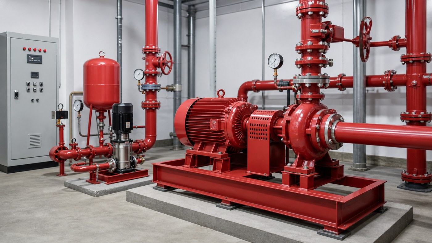
Vertical inline fire pump installation requires compliance with NFPA 20 standards, proper foundation support, adequate clearance for maintenance, correct suction piping arrangement, dedicated electrical service with automatic transfer capability, and documented acceptance testing. The installation must accommodate pump removal without draining the system, provide access to the motor and mechanical seal, and ensure the pump can reach rated capacity at churn pressure without cavitation. This guide explains the mandatory requirements, common field errors, and the verification steps that separate compliant installations from expensive rebuilds.
Key Takeaways
- NFPA 20 governs fire pump installations and supersedes general pump practice; verify local adoption and amendment status before design.
- Foundation and support must carry operating loads, transient pressure surges, and maintenance access weight without deflection or misalignment.
- Suction piping must be sized for net positive suction head requirements, avoid air pockets, and include isolation valves with supervisory switches.
- Electrical service requires dedicated circuits, automatic transfer to emergency power, and controller compliance with UL 218 or FM approval.
- Acceptance testing is mandatory and must document flow, pressure, power draw, and performance across the full pump curve before final approval.
Foundation and Structural Support Requirements
Vertical inline fire pumps impose concentrated radial and axial loads at the pipe connection points. The foundation must support the pump assembly weight, dynamic operating forces, and the weight of a service technician during maintenance. Concrete pads should extend at least six inches beyond the pump base in all directions and be isolated from building structural loads to prevent differential settlement.
The pump must be independently supported by its mounting flange or base plate, not by the piping system. While the pump connects inline with the piping, the pipe cannot carry the pump weight without eventual misalignment. Install rigid pipe supports within two pipe diameters of each pump connection, and provide flexible couplings or expansion joints if thermal movement exceeds 0.1 inches. Anchor the discharge pipe separately to prevent thrust forces from shifting the pump during startup or pressure transients.
Check floor loading capacity before installation. A typical vertical inline fire pump with motor can weigh 800 to 2,500 pounds depending on size and construction. Add the weight of water in the pump and connected piping, then verify the floor can support at least 150 percent of the static load to account for dynamic forces and maintenance equipment.
Suction Piping and NPSH Considerations
Fire pump suction piping must deliver adequate net positive suction head at all flow rates up to 150 percent of rated capacity. NFPA 20 requires suction pipe diameter to equal or exceed the pump suction connection size, with no reducers, restrictions, or abrupt directional changes within ten pipe diameters of the pump inlet. Eccentric reducers must be installed flat-side-up to prevent air pocket formation.
The suction line must slope continuously upward toward the pump when drawing from a tank or reservoir below pump level. Any horizontal run creates a potential air trap. For systems drawing from elevated tanks or suction sources above the pump, slope the line downward toward the pump and install a check valve at the tank outlet to maintain prime. The suction isolation valve must be an OS&Y gate valve with a supervisory tamper switch that alarms if the valve moves from the fully open position.
Calculate available NPSH using the actual suction source elevation, atmospheric pressure, vapor pressure at operating temperature, and measured pipe friction losses. Fire pumps typically require 15 to 25 feet of NPSH depending on specific speed and impeller design. Provide at least a three-foot margin above the required value. If available NPSH is marginal, enlarge the suction pipe, shorten the suction run, or raise the suction source rather than accepting borderline conditions that will cause cavitation during emergency operation.
| Suction Configuration | Minimum Pipe Size | Key Risk | Mitigation |
|---|---|---|---|
| Suction lift from reservoir | One size larger than pump inlet | Air ingress, loss of prime | Foot valve, priming connection, continuous upward slope |
| Flooded suction from elevated tank | Equal to pump inlet minimum | Valve closure, air pockets | Supervisory switch, high-point vents, downward slope |
| Suction from underground storage | One size larger than pump inlet | Sediment, entrained air, low NPSH | Inlet bell submerged 2× diameter, minimum water level interlock |
Electrical Service and Control Requirements
Fire pumps require dedicated electrical service independent of the building’s normal power distribution. The service must originate ahead of the main building disconnect so that a building electrical fault or maintenance shutdown does not de-energize the fire pump. Install an automatic transfer switch rated for the full locked-rotor current of the fire pump motor, with transfer time under ten seconds. The transfer switch must provide power from both normal and emergency sources, typically utility and on-site generator.
Fire pump controllers must be listed to UL 218 or approved by FM Global. Standard motor starters, variable frequency drives, and soft-start controllers are not acceptable unless specifically listed for fire pump service. The controller must provide phase loss protection, phase reversal protection, and running overload indication without automatic shutdown. Fire pumps are allowed to run to failure during an emergency, so the controller does not trip on overload—it only alarms.
Size conductors for 125 percent of the motor full-load current with no additional safety factor. Fire pump circuits are exempt from some National Electrical Code requirements that would otherwise require larger wire sizes. However, voltage drop from the service point to the motor terminals must not exceed five percent at locked rotor current and three percent at full load current. For long runs or large motors, this often dictates conductors several sizes larger than the ampacity requirement alone would suggest.
Install a dedicated ground rod at the fire pump location and bond it to the building grounding system. Verify rotation direction before coupling the motor to the pump. Incorrect rotation will produce near-zero discharge pressure and can damage the impeller or seal faces within seconds. Check rotation with the coupling disconnected and motor jogged, or measure phase sequence at the controller terminals and confirm against the motor nameplate diagram.
Clearance and Maintenance Access
NFPA 20 requires adequate space around the fire pump for inspection, testing, and maintenance without system shutdown. Provide at least three feet of clearance on all sides of the pump and motor assembly. For pumps larger than 100 horsepower or installations requiring crane access for motor removal, increase clearance to accommodate lifting equipment and component laydown space.
The pump must be removable without draining the fire protection system. Install flanged isolation valves on both suction and discharge sides with sufficient pipe length to separate flanges and slide the pump assembly out axially. If space constraints prevent full pump removal, provide a split-case design or plan for system draining and refilling during major service. Document the service procedure and confirm lifting point capacity before acceptance.
Locate the pump room to protect against freezing, flooding, and unauthorized access while allowing rapid access for emergency responders. The room must have adequate ventilation to prevent motor overheating during extended operation. For enclosed spaces, provide ventilation equal to 1 CFM per HP of motor rating or follow the motor manufacturer’s specific requirement, whichever is greater.
Acceptance Testing and Commissioning
NFPA 20 requires witnessed acceptance testing before the fire pump can be placed in service. The test must demonstrate that the pump delivers rated flow at rated pressure, operates at churn pressure without damage, and reaches 150 percent of rated flow with no evidence of cavitation or motor overload. Conduct the test with flow meters, pressure gauges, and power meters that meet the accuracy requirements in NFPA 20 Chapter 14.
Record performance at no-flow (churn), 100 percent rated flow, and 150 percent rated flow. At each test point, measure suction pressure, discharge pressure, motor voltage, motor amperage on all three phases, and pump speed. Calculate total head, water horsepower, brake horsepower, and pump efficiency. Compare the results to the certified pump curve. The pump must operate within the published performance range and must not overload the motor at any point on the curve up to 150 percent of rated flow.
If the pump fails to meet rated performance, check rotation direction first, then inspect for suction restrictions, discharge valve position, air in the system, or incorrect impeller diameter. Do not adjust trim or operating speed to compensate for a selection error or installation problem. If the pump cannot meet the required duty, identify the root cause and correct it. Common issues include undersized suction piping, excessive lift, clogged strainers, throttled valves, or incorrect pump model selection.
Document all test data, including atmospheric pressure, water temperature, flow rates, pressures, electrical values, and vibration readings. Provide a copy of the test report to the authority having jurisdiction and retain a copy with the fire pump maintenance records. Schedule annual flow tests to verify continued performance and detect wear or system changes that might affect pump capacity.
Frequently Asked Questions
Can I install a vertical inline fire pump in a horizontal orientation to save space?
No. Vertical inline pumps are designed for vertical shaft operation with the motor mounted above the pump. Horizontal installation changes bearing loads, seal face contact, and thrust balance. If space requires a horizontal pump, specify a horizontal split-case or end-suction fire pump instead. Converting a vertical pump to horizontal operation will void the listing and violate NFPA 20 compliance.
What happens if I install a VFD to control the fire pump speed?
Fire pumps must operate at full speed and full capacity when activated. Variable frequency drives are prohibited unless the complete pump, motor, and drive assembly is listed as a unit for fire pump service. Standard industrial VFDs will not meet NFPA 20 requirements for automatic start, phase monitoring, and emergency operation. Most fire pump applications use fixed-speed across-the-line or reduced-voltage starting only.
Do I need a jockey pump with a vertical inline fire pump installation?
A jockey pump is not part of the vertical inline fire pump installation itself, but most fire protection systems include one to maintain system pressure without starting the main fire pump. The jockey pump is a separate small pump that compensates for minor leaks and pressure variations. It prevents nuisance starts of the main fire pump and reduces wear, but it is not required by NFPA 20 if the system is tight and pressure remains stable.
How do I verify the pump is sized correctly if the original design calculations are missing?
Measure the actual system demand by flowing water through the most hydraulically remote sprinkler or hose connection and recording the flow rate and residual pressure. Compare this to the pump curve at the measured flow to confirm the pump can deliver adequate pressure. If the system has been modified since original installation—added sprinklers, extended piping, or increased hazard classification—the existing pump may no longer be adequate. Recalculate the hydraulic demand using current system configuration and compare to pump capacity.
Can I replace just the motor and reuse the existing pump assembly?
Only if the replacement motor matches the original horsepower, speed, frame, and shaft dimensions exactly. Fire pump assemblies are tested and listed as complete units. Substituting a different motor can change starting characteristics, overload protection coordination, and mechanical fit. If the motor has failed due to electrical fault, replacement with an identical model is acceptable. If the motor failed due to overload or frequent starts, investigate the system cause before replacing the motor, or the new motor will fail the same way.
Conclusion
Vertical inline fire pump installation is governed by specific code requirements that differ substantially from general pump practice. Verify NFPA 20 compliance at every stage: foundation support, suction piping arrangement, dedicated electrical service, maintenance clearances, and documented acceptance testing. If the installation must support emergency life-safety systems, do not approximate or substitute. Follow the standard, document the test results, and confirm the pump can deliver rated performance under actual operating conditions. An installation that looks correct but fails the flow test is not compliant and must be corrected before the system can be approved for service.