
Flow and head calculations for vertical inline pumps are not academic exercises—they determine whether your pump will deliver the required performance or fail within weeks of installation. The calculation process combines system requirements (flow rate, total dynamic head) with pump curve data, NPSH margins, and motor specifications to verify that the selected pump can operate efficiently at the duty point. Most field failures trace back to mismatches between calculated conditions and actual site variables: suction lift errors, friction loss underestimation, control logic interference, or voltage issues that prevent the motor from reaching design speed.
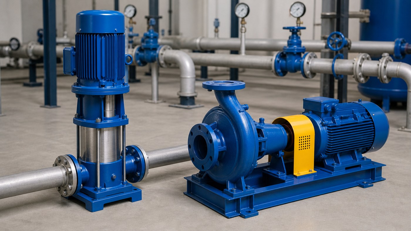
Key Takeaways
- Flow and head define the duty point, but suction conditions, liquid properties, motor data, and control settings determine whether the pump will actually meet that duty point reliably.
- Total dynamic head includes static lift, friction losses in suction and discharge piping, pressure head requirements, and velocity head—never calculate using static lift alone.
- NPSH available must exceed NPSH required by an adequate margin; for inline pumps with suction lift, this margin often dictates maximum practical lift height.
- Pump curves show performance at rated speed and clean water; correction factors apply for viscosity, specific gravity, and speed variations.
- Verify the operating point falls within the pump’s preferred operating region (typically 80-110% of best efficiency point) to avoid cavitation, recirculation, or excessive wear.
Calculating Total Dynamic Head
Total dynamic head (TDH) is the total energy the pump must impart to move liquid from source to destination. Start with static head: the vertical distance from the liquid surface at suction to the discharge point. For flooded suction arrangements common with inline pumps, static head may be negative if the source is above the pump centerline.
Add friction losses for both suction and discharge piping. Use the Darcy-Weisbach or Hazen-Williams equations with actual pipe length, fittings count, and valve positions. A 100-foot run of 4-inch Schedule 40 pipe at 200 GPM typically adds 3-5 feet of friction loss, but this doubles with gate valves, elbows, and tees. Do not estimate friction loss from a different flow rate and scale it—friction loss increases with the square of velocity.
If the discharge terminates at a pressurized vessel or elevation-controlled header, convert the required pressure to feet of head by multiplying PSI by 2.31 and dividing by specific gravity. For water at standard conditions, 10 PSI equals 23.1 feet of head.
Velocity head (V²/2g) is usually negligible for inline pumps operating below 10 feet per second pipe velocity, but include it for accuracy in high-velocity applications or when discharge velocity differs significantly from suction velocity.
Determining Required Flow Rate
Flow rate comes from system demand, not pump preference. For HVAC circulation, calculate from heat load and temperature differential: GPM = (BTU/hr) / (500 × ΔT°F). A 1,000,000 BTU/hr load with 20°F differential requires 100 GPM. For process cooling or industrial makeup water, measure or estimate consumption rates during peak demand periods.
Fire pump flow rates are dictated by NFPA 20 and sprinkler system hydraulic calculations—these are non-negotiable and must include hose stream allowances. Wastewater and lift station pumps size to peak inflow rates with enough margin to prevent excessive cycling, typically 3-6 starts per hour maximum.
Account for future expansion if the system will grow within the pump’s service life. Oversizing by 10-15% provides operational flexibility, but excessive oversizing forces the pump to operate left of its best efficiency point, increasing energy consumption and accelerating wear.
NPSH Considerations for Inline Pumps
Net positive suction head available (NPSHa) must exceed the pump’s required NPSH (NPSHr) by at least 3-5 feet for reliable operation. For vertical inline pumps with suction lift, calculate NPSHa as atmospheric pressure (in feet of liquid) minus suction lift, minus friction losses in suction piping, minus vapor pressure of the liquid at operating temperature.
At sea level with 60°F water, atmospheric pressure provides 34 feet. A pump with 10 feet of suction lift, 2 feet of suction friction loss, and 0.6 feet vapor pressure has 21.4 feet NPSHa. If the pump requires 15 feet NPSHr, the margin is adequate. At 180°F water, vapor pressure jumps to 20 feet, reducing NPSHa to 1.4 feet—cavitation is guaranteed.
Flooded suction arrangements eliminate most NPSH problems by placing the pump below the liquid source. This is why inline pumps in basement mechanical rooms or below-grade pits handle hot water reliably while rooftop installations struggle.
Matching Pump Curve to System Curve
The system curve plots head versus flow based on static head and friction losses. Since friction increases with flow squared, the system curve is parabolic. The pump curve shows the head the pump produces at various flow rates. The intersection is the operating point.
Plot both curves to verify the operating point falls within the pump’s efficient range. If the operating point sits far right (high flow, low head), the pump is oversized and will overload the motor. If it sits far left (low flow, high head), flow recirculation and cavitation damage will occur.
Control valves artificially steepen the system curve by adding resistance. While throttling works for temporary adjustments, permanent throttling wastes energy. If the pump consistently operates with a discharge valve 50% closed, the pump is oversized for the actual system requirements.
Motor and Electrical Considerations
Verify motor horsepower exceeds the brake horsepower required at the operating point by at least 10-15% service factor. Calculate brake horsepower as (GPM × TDH × Specific Gravity) / (3960 × Pump Efficiency). A 200 GPM pump running at 100 feet TDH with 70% efficiency requires 7.2 BHP; a 10 HP motor provides adequate margin.
Confirm voltage matches site supply. Running a 460V motor on 440V reduces speed approximately 4%, shifting the pump curve downward and potentially causing motor overheating. Three-phase motors must have correct rotation direction—inline pumps typically show rotation direction on the motor housing or nameplate.
Variable frequency drives allow operating point adjustments by changing motor speed. Since pump performance follows affinity laws (flow changes proportionally with speed, head with speed squared, power with speed cubed), a 20% speed reduction cuts power consumption nearly in half while reducing flow by 20% and head by 36%.
Common Calculation Errors
Using nameplate data without checking the pump curve. A pump rated “10 HP, 200 GPM” does not deliver 200 GPM at every head—that flow occurs only at the rated head shown on the curve.
Forgetting to account for fittings and valves in friction loss calculations. Two gate valves, four elbows, and a check valve can add 15-20 equivalent feet of straight pipe.
Ignoring temperature effects on viscosity and vapor pressure. Water at 200°F has half the viscosity and twenty times the vapor pressure of 60°F water, dramatically affecting pump performance and NPSH requirements.
Assuming suction pressure equals atmospheric pressure. Open tanks provide atmospheric pressure minus liquid surface elevation loss. Closed vessels operate at whatever pressure the system maintains, which may be above or below atmospheric.
Frequently Asked Questions
Can I use the same calculation method for sewage and clean water pumps?
The hydraulic calculations remain the same, but sewage pumps require larger impeller passages to handle solids without clogging, which typically reduces efficiency by 5-10% compared to clean water pumps of the same size. Use the actual pump curve for the sewage-handling model, not a clean water equivalent.
How do I calculate head when the discharge point elevation varies?
Use the maximum expected discharge elevation for sizing. If a pump fills tanks at different levels, calculate TDH for the highest tank. The pump will operate at higher flow and lower power when filling lower tanks, which is acceptable. Sizing for minimum head causes motor overload when filling the highest point.
What causes a pump to deliver less flow than calculated?
Air leaks in suction piping, incorrect rotation direction, worn wear rings or impeller, system blockages increasing actual friction loss beyond calculated values, reduced motor speed due to voltage or frequency issues, or cavitation from insufficient NPSHa. Measure actual suction and discharge pressure, then plot the operating point against the pump curve to diagnose the problem.
Do I need to recalculate if I replace the pump with the same model?
Only if the system changed. New piping, additional equipment, modified control logic, different liquid properties, or changed operating conditions require recalculation. If the replacement occurs because the original pump failed, investigate why—incorrect original selection often causes repeated failures with identical replacements.
How do I account for parallel or series pump operation?
Parallel pumps add flow capacity at the same head—plot both pump curves and add flows at each head value. Series pumps add head at the same flow—add head values at each flow point. The combined curve intersects the system curve at the new operating point. Neither arrangement doubles capacity in real systems due to the system curve shape.
Conclusion
Accurate flow and head calculations prevent costly installation failures, but the calculation is only as reliable as the input data. Measure static elevations, count fittings, verify liquid properties, check electrical supply, and obtain actual pump curves from the manufacturer rather than relying on generic performance ranges. After installation, test the pump at the design operating point by measuring suction pressure, discharge pressure, flow rate, and motor current to confirm the calculated duty point matches field reality. When the numbers do not align, investigate system conditions before blaming the pump—most performance problems trace to installation details, control interference, or unaccounted system resistance rather than pump defects.