
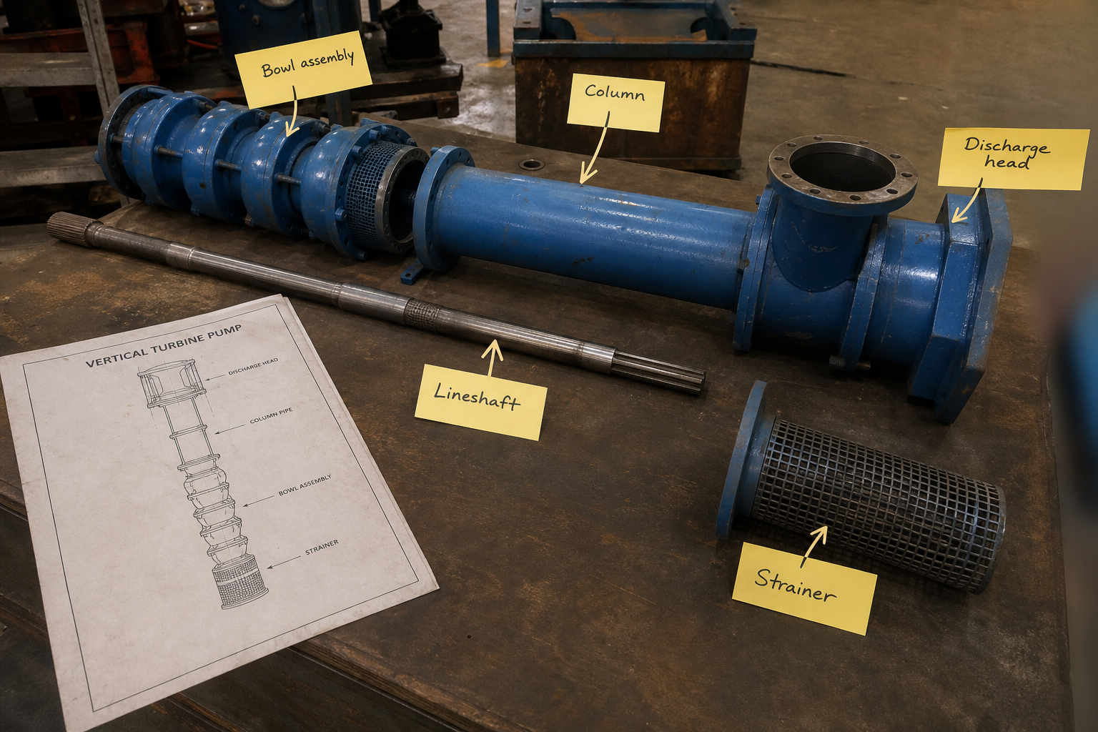
Field-style article image prepared for vertical turbine pump diagram.
When you specify a vertical turbine pump for a 180-foot municipal well, the diagram shows four stacked assemblies that determine flow capacity, total head, shaft speed, and installation clearance. The bowl assembly houses the impeller stages at the bottom. The column pipe carries discharge flow upward while supporting the lineshaft that rotates inside it. The discharge head mounts at grade level and connects the driver to the lineshaft while directing flow into the discharge piping.
Each component on the diagram controls a different performance variable. Bowl-assembly length sets total head by staging multiple impellers in series. Column length matches well depth and water level. Lineshaft design affects bearing intervals and shaft whip limits. Discharge-head configuration determines whether you use a surface motor or a right-angle gear drive.
Key Takeaways
- Bowl assembly diagrams show impeller stages stacked vertically with diffuser bowls between each stage; total stages equal total head divided by head per stage
- Column pipe length extends from the bowl assembly suction bell to grade level and contains the lineshaft, product bearings, and discharge flow path
- Lineshaft diameter and bearing spacing determine critical speed limits; shaft must run below the first critical speed for continuous operation
- Discharge head connects the motor or right-angle drive to the lineshaft top coupling and redirects vertical flow to horizontal discharge piping
Bowl Assembly Configuration and Stage Count
The bowl assembly sits at the pump suction end, submerged below the pumping water level. Each stage consists of an impeller that adds velocity and a diffuser bowl that converts velocity to pressure head.
Single-stage bowl assemblies generate 20 to 80 feet of head per stage depending on impeller diameter and speed. Multi-stage designs stack identical stages on a common shaft. A four-stage pump with 50 feet per stage delivers 200 feet total dynamic head.
Bowl diameter ranges from 4 inches to 48 inches. Smaller bowls fit inside well casings; larger bowls mount in open sumps or intake structures. The suction bell at the bottom of the bowl assembly guides flow into the first impeller eye with minimum turbulence.
Impellers are enclosed, semi-open, or fully open depending on fluid cleanliness. Enclosed impellers with front and back shrouds handle clean water with highest efficiency. Semi-open designs tolerate sand and grit. Fully open impellers pass fibrous solids in wastewater or irrigation applications.
Column Pipe and Bearing Assembly Layout
Column pipe connects the bowl assembly discharge to the surface discharge head. Standard pipe sections are 10 or 20 feet long, flanged or threaded at each joint.
The column serves three functions. First, it carries pumped liquid from the bowl discharge upward to grade level. Second, it supports the lineshaft mechanically through internal product bearings or external steady bearings. Third, it provides structural support for the entire pump assembly suspended in the well or sump.
Product bearings mount inside the column at regular intervals, typically every 5 to 10 feet. These bearings are lubricated by the pumped liquid and guide the lineshaft to prevent whip and vibration. Bearing material must be compatible with the pumped fluid—bronze or rubber for clean water, tungsten carbide or ceramic for abrasive slurries.
Column pipe material is carbon steel, stainless steel, or fiberglass-reinforced plastic. Material selection depends on fluid corrosivity, temperature, and pressure rating. Wall thickness must withstand collapse pressure if the pump runs in a vacuum condition during priming.
Lineshaft Drive Types and Critical Speed
The lineshaft transmits torque from the surface driver down to the bowl-assembly impeller shaft. Two lineshaft configurations appear on vertical turbine pump diagrams: enclosed shaft with oil lubrication or open shaft with product lubrication.
Enclosed-shaft pumps use a shaft tube surrounding the lineshaft. The tube contains oil that lubricates bronze or ball bearings at each coupling joint. An external oil reservoir at the discharge head supplies oil to the shaft tube. This design protects bearings from contaminated water but requires regular oil maintenance.
Open-shaft pumps rely on the pumped liquid to lubricate product bearings. No shaft tube or oil system is needed. This simplifies maintenance but limits bearing materials to those compatible with the fluid.
Lineshaft diameter and length determine critical speed—the shaft speed at which lateral vibration resonates and damages bearings. The first critical speed for a simply-supported shaft is:
N_c = 60 × √(g × E × I / (W × L³))
where N_c is critical speed in RPM, g is gravitational acceleration, E is shaft modulus of elasticity, I is shaft moment of inertia, W is shaft weight per unit length, and L is bearing span length.
Safe operating speed must stay below 70 percent of first critical speed for continuous duty. For a 150-foot column with bearing spacing at 10-foot intervals, typical lineshaft diameters range from 1.25 to 2.5 inches to keep 1,750 or 3,500 RPM motor speeds below critical limits.
Discharge Head Assembly and Driver Mounting
The discharge head bolts to the top column flange at grade level. It performs four functions: supports the motor or gear drive, couples the driver shaft to the lineshaft, redirects vertical flow to horizontal discharge, and provides stuffing box or mechanical seal at the lineshaft penetration.
Two driver configurations appear on discharge-head diagrams. Direct-coupled vertical hollow-shaft motors mount directly above the discharge head with the motor shaft sleeved over the lineshaft coupling. This is the most compact arrangement and eliminates belts or gears.
Right-angle gear drives mount horizontally beside the discharge head. A bevel gear set couples the horizontal motor shaft to the vertical lineshaft. This configuration suits locations where vertical clearance is limited or where speed reduction is needed between motor and pump.
The discharge elbow turns flow 90 degrees from vertical column discharge to horizontal piping. Elbow design affects head loss; long-radius elbows reduce friction loss compared to short-radius designs.
Stuffing boxes with packing rings or mechanical seals prevent leakage where the lineshaft penetrates the discharge head. Mechanical seals require less maintenance than packing but cost more initially. The seal faces must be compatible with fluid temperature and pressure.
Installation Depth and Submergence Requirements
Vertical turbine pump diagrams show three elevation dimensions that control installation layout and performance.
Bowl setting depth is the vertical distance from grade level to the bowl assembly suction bell. This depth must place the suction bell below minimum expected water level with additional submergence to prevent vortexing.
Required submergence over the suction bell ranges from 1.5 to 3 times the bell diameter depending on flow rate. Insufficient submergence causes air entrainment, cavitation, and loss of prime. Deep-well pumps in municipal or irrigation service often set bowls 50 to 300 feet below static water level to account for seasonal drawdown.
Column length equals bowl setting depth plus the distance from grade to the discharge-head mounting flange. If the discharge head mounts in a below-grade pump pit, column length may be shorter than bowl setting depth.
Pump capacity decreases if actual submergence falls below design submergence. Vortex formation at the suction bell admits air into the first impeller stage, reducing pressure rise per stage and total head output.
Component Selection Table
Component | Selection Driver | Range | Constraint |
Bowl diameter | Well casing ID, flow rate | 4–48 in | Minimum 2-in clearance to casing |
Stage count | Total head requirement | 1–20 stages | Head per stage typically 20–80 ft |
Column length | Pump setting depth | 10–500 ft | Must clear minimum water level |
Lineshaft diameter | Critical speed, torque | 0.75–3 in | Operating speed <70% first critical |
Bearing spacing | Shaft support, critical speed | 5–10 ft | Closer spacing for long columns |
Discharge head type | Driver mounting, clearance | Vertical motor, right-angle gear | Vertical motor needs overhead clearance |
FAQs
How do you calculate the number of bowl stages needed?
Divide total dynamic head by the head per stage from the pump curve. Round up to the next whole number. For example, 240 feet TDH with a bowl rated at 55 feet per stage requires 240 ÷ 55 = 4.36, rounded to 5 stages. The extra capacity provides operating margin.
Can you add column sections to an existing vertical turbine pump?
Yes, if the water level drops below the original setting depth. Remove the pump, add flanged column sections, extend the lineshaft with couplings, and reset the pump at greater depth. Verify that shaft critical speed remains acceptable with the longer lineshaft length.
What causes lineshaft vibration in vertical turbine pumps?
Operating speed near or above critical speed excites resonant vibration. Worn product bearings allow shaft whip. Bent shafting from installation damage causes runout. Cavitation at the bowl suction creates pressure pulsations that travel up the shaft. Check bearing condition, verify submergence, and confirm operating speed is below 70 percent of first critical.
Do all vertical turbine pumps use lineshafts?
No. Submersible vertical turbine pumps place the motor below the bowl assembly on the same shaft. No lineshaft is needed because the motor sits in the well. This eliminates shaft critical-speed concerns but requires waterproof motor construction and pull-out for motor service.
Conclusion
A vertical turbine pump diagram shows you how bowl-assembly stage count sets head capacity, column length matches installation depth, lineshaft design limits operating speed, and discharge-head type determines driver mounting. Before ordering, confirm total dynamic head to size bowl stages, measure setting depth to static and pumping water levels for column length, calculate lineshaft critical speed against available motor speeds, and verify discharge-head configuration fits site clearance and piping layout. Send the pump manufacturer your flow rate, total head, fluid properties, setting depth, well casing diameter, and driver preference to receive a complete sectional drawing with component part numbers and performance curves.