
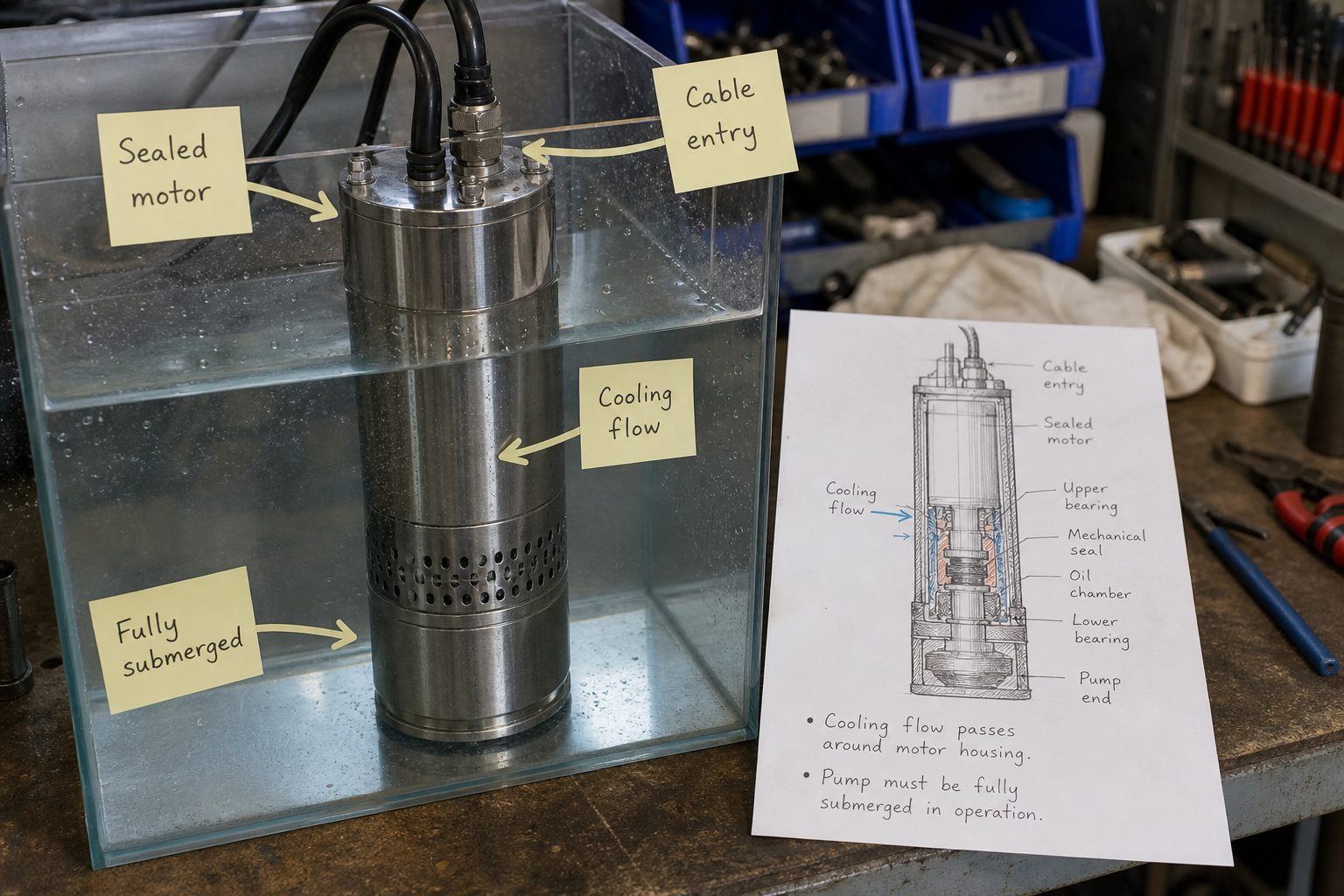
Field-style article image prepared for what is a submersible pump.
A submersible pump is a centrifugal or positive-displacement pump with a sealed motor designed to operate fully submerged in the pumped fluid. The defining feature is not the hydraulic end but the motor construction: hermetically sealed windings, liquid-filled motor chambers, and a cooling path that relies on heat transfer to the surrounding fluid rather than forced air.
Engineers frequently size submersible pumps using surface-pump formulas, then discover the motor runs hot or the seal fails within weeks. The error is treating submersion as optional. A submersible motor produces 30-50% more waste heat per kilowatt than an equivalent air-cooled motor because the sealed enclosure traps heat. Without adequate liquid velocity past the motor housing—typically 0.3 m/s minimum—the motor overheats regardless of nameplate margin.
This article explains how motor sealing and liquid cooling define a submersible pump, the operating limits imposed by fluid properties and installation geometry, and the conditions under which submersion becomes infeasible.
Key Takeaways
- A submersible pump’s motor is sealed and cooled by the surrounding fluid; it cannot operate in air without immediate thermal damage.
- Minimum submersion depth is set by net positive suction head required (NPSHr) plus a margin to prevent vortex formation at the intake, typically 0.5-1.0 m above the impeller centerline.
- Fluid viscosity above 200 cP and solids concentration above 10% by weight require derating or specialized sealing to prevent abrasive wear and seal failure.
- Maximum operating depth is limited by static pressure on shaft seals and motor housing, typically 150-300 m depending on seal design and casing material.
Motor Sealing and Hermetic Construction
A submersible motor uses a sealed stator chamber filled with dielectric oil or water-glycol mixture to equalize pressure and prevent fluid ingress. The rotor shaft passes through mechanical seals—typically double or tandem carbon-ceramic faces with an oil barrier chamber between the motor and hydraulic end.
Seal pressure rating determines maximum operating depth. A standard elastomer-face seal rated to 10 bar limits depth to roughly 100 m of water column. Hard-face seals with silicon carbide or tungsten carbide extend the range to 200-300 m but require clean fluid to prevent abrasive particle jamming.
Cable entry presents a secondary seal point. Submersible cable glands use compression seals and potting compound to prevent wicking along conductor strands. If the cable jacket is nicked during installation, water migrates into the motor within hours, causing winding insulation failure.
Liquid Cooling and Heat Rejection Limits
Air-cooled motors rely on shaft-mounted fans and finned enclosures to dissipate 20-30 W per kilogram of motor mass. Submersible motors reject 40-60 W/kg directly to the fluid through the motor housing.
Heat transfer depends on fluid velocity past the housing and the temperature difference between the motor surface and bulk fluid. The relationship follows Newton’s law of cooling:
Q = h × A × ΔT
Where:
- Q = heat rejected, watts
- h = convective heat transfer coefficient, W/(m²·K)
- A = motor housing surface area, m²
- ΔT = temperature difference between motor surface and fluid, K
For water at 0.3 m/s flow velocity, h ≈ 500-800 W/(m²·K). For stagnant water, h drops to 50-100 W/(m²·K), reducing heat rejection capacity by 80-90%. This is why submersible pumps installed in narrow wells or storage tanks with minimal circulation require derating or external flow inducers.
Operating Depth and Suction Limits
Minimum submersion depth must satisfy two constraints: net positive suction head available (NPSHa) must exceed NPSHr, and the intake must sit deep enough to prevent surface vortex formation.
NPSHa at the impeller eye equals:
NPSHa = (P_atm / ρg) + H_sub – (P_vap / ρg) – h_f
Where:
- P_atm = atmospheric pressure, Pa (101,325 Pa at sea level)
- ρ = fluid density, kg/m³
- g = gravitational acceleration, 9.81 m/s²
- H_sub = submersion depth above impeller centerline, m
- P_vap = fluid vapor pressure at operating temperature, Pa
- h_f = friction loss in suction piping, m
For water at 20°C (P_vap ≈ 2,340 Pa), a pump requiring 3.0 m NPSHr needs at least 3.5 m submersion to provide 0.5 m safety margin. In hot water at 80°C (P_vap ≈ 47,400 Pa), the required submersion increases to 8-9 m.
Vortex prevention typically requires 0.5-1.0 m additional depth beyond the NPSHr minimum, depending on intake diameter and flow rate.
Maximum depth is constrained by seal pressure rating and motor housing strength. Standard designs handle 10-15 bar static pressure; high-pressure variants extend to 30 bar (300 m depth in fresh water).
Fluid Property Constraints
Fluid Property | Standard Limit | Effect When Exceeded | Mitigation |
Viscosity | 200 cP | Reduced cooling velocity; increased bearing friction | Hard-face seals; oversized motor |
Solids concentration | 10% by weight | Abrasive seal wear; impeller erosion | Flush plans; wear-resistant coatings |
Temperature | 40°C continuous | Reduced motor insulation life; seal elastomer degradation | Class F or H insulation; EPDM seals |
Corrosivity | pH 6-9 | Seal spring corrosion; housing pitting | 316 SS wetted parts; Viton seals |
Submersible pumps handling sewage, slurries, or chemically aggressive fluids require application-specific sealing and materials. A pump rated for clean water will fail within days in 15% solids slurry due to abrasive seal face damage.
Installation Configuration and Control
Submersible pumps operate in three primary configurations: well-casing suspension (pump hangs from discharge pipe), sump-pit mounting (pump rests on guide rails or base), and open-water deployment (pump suspended by cable and hose).
Well-casing installations limit motor cooling to the natural upward flow past the housing as water enters the well screen. If well yield drops below 0.1 L/s per kilowatt of motor rating, cooling becomes insufficient. A 5 kW pump drawing 0.3 L/s in a 150 mm casing generates only 0.17 m/s flow velocity, below the 0.3 m/s cooling minimum.
Level control must prevent dry running. A submersible motor exposed to air for more than 30 seconds reaches thermal shutdown. Float switches are common but fail open-circuit in cable fault conditions. Redundant pressure transducers or ultrasonic level sensors provide fail-safe shutdown.
Frequent starts degrade motor bearings and seals due to thermal cycling. Motors rated for 10 starts per hour operate reliably in automatic sump drainage. Those rated for 2-3 starts per hour are intended for constant-speed well service and will fail prematurely under on-off cycling.
FAQs
Can a submersible pump run partially submerged?
No. The motor must remain fully submerged during operation. Partial submersion exposes the motor housing to air, eliminating convective cooling and causing thermal overload within minutes. Installation should include low-level cutoff set 0.3-0.5 m above the motor top.
How deep can a standard submersible pump operate?
Most standard industrial submersible pumps are rated to 100-150 m depth, corresponding to 10-15 bar static pressure. Specialized deep-well models with high-pressure seals and reinforced housings extend to 300 m. Beyond this depth, multistage surface pumps with lineshaft drive or submersible turbine pumps become more economical.
What causes a submersible pump to overheat in cold water?
Overheating in cold water indicates insufficient flow velocity past the motor housing, not inadequate fluid temperature. If the pump is installed in a narrow well casing, storage tank, or sump with minimal circulation, convective heat transfer drops below the motor’s heat rejection requirement. Verify flow velocity exceeds 0.3 m/s or install flow-inducing shrouds.
Do submersible pumps require external lubrication?
No. The motor chamber is pre-filled with dielectric oil or water-glycol mixture that lubricates bearings and provides pressure equalization. External lubrication ports are limited to seal flush systems on pumps handling abrasive or solids-laden fluids, where clean barrier fluid is injected between the motor and hydraulic end.
Conclusion
A submersible pump is defined by its sealed motor construction and dependence on liquid cooling, not by the choice of centrifugal or positive-displacement hydraulic design. The motor must remain fully submerged with adequate flow velocity past the housing—typically 0.3 m/s minimum—or thermal failure will occur regardless of fluid temperature.
Selection starts with confirming minimum submersion depth exceeds NPSHr plus vortex margin, verifying maximum operating depth remains within seal pressure rating, and checking that fluid viscosity, solids concentration, and temperature fall within the pump’s material and sealing limits. Installations with restricted flow, high cycling duty, or fluids outside the standard water range require derating, upgraded seals, or specialized motor enclosures. Before specifying a submersible pump, confirm well yield, sump geometry, or deployment depth against these cooling and pressure constraints.