
A vertical inline pump mounts directly in the pipeline with the motor on top and the impeller below, eliminating the need for a separate base or coupling guard. The shaft runs vertically through a column or casing, and the impeller pushes liquid upward through the discharge connection. This design saves floor space, simplifies alignment, and allows installation in tight mechanical rooms, but it requires careful attention to suction conditions, shaft support, and seal cooling to avoid premature failure.
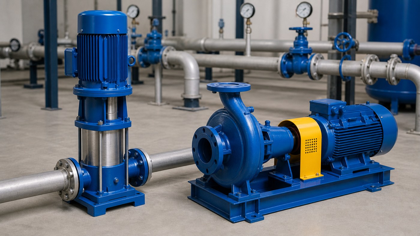
The pump works by rotating the impeller inside a volute or diffuser casing. Liquid enters through the suction port at the bottom, accelerates through the impeller vanes, and exits through the discharge port at the top or side. The vertical shaft is supported by bearings in the motor or a bracket assembly, and mechanical seals prevent leakage where the shaft passes through the casing. Most vertical inline pumps are centrifugal designs rated for clean or lightly contaminated water in HVAC, boosting, circulation, and light industrial service.
Key Takeaways
- Vertical inline pumps save space by mounting in the pipe, but they depend on proper suction pressure and cannot tolerate significant pipe strain or misalignment.
- Check the pump curve against total dynamic head, not just discharge pressure, and confirm the motor can handle the actual operating point.
- Seal and bearing life depend on liquid temperature, solids content, operating hours, and adequate cooling flow through the seal chamber.
- For fire, high-temperature, or continuous-duty applications, verify that the pump is rated and listed for that service, not just sized for the flow and head.
- Include flow, head, liquid type, temperature, suction condition, voltage, and installation position in any quotation or service request.
Physical Design and Operating Principle
A vertical inline pump consists of a motor mounted on top of a pump casing with the impeller attached to a vertical shaft. The impeller is enclosed in a volute or diffuser chamber, and the discharge nozzle is typically perpendicular to the suction. The entire assembly is supported by flanges that bolt directly to the pipeline, so the pump becomes part of the piping system rather than sitting on a separate base.
When the motor starts, the impeller rotates and creates a low-pressure zone at the eye. Liquid is drawn into the impeller from the suction pipe, accelerated outward by centrifugal force, and discharged into the volute where velocity is converted to pressure. The liquid then exits through the discharge connection and continues through the system. The process is continuous as long as the suction line is filled and the impeller is submerged or flooded.
Bearing support can come from the motor itself or from a separate bearing bracket between the motor and pump. Single-stage pumps have one impeller, while multistage pumps stack several impellers on the same shaft to generate higher head. Mechanical seals or packing rings prevent liquid from leaking along the shaft, and seal flushing or cooling may be required depending on the liquid temperature and duty cycle.
Where Vertical Inline Pumps Are Used
Vertical inline pumps are common in HVAC systems for chilled water, hot water, and condenser water circulation. They fit into tight mechanical rooms where horizontal pumps would require excessive floor space or additional piping. Building engineers choose them for booster sets, domestic water pressure systems, and closed-loop heating or cooling circuits.
Industrial applications include washdown systems, process water transfer, cooling tower circulation, and light chemical service when the pump materials are compatible. Fire protection systems sometimes use vertical inline jockey pumps to maintain pressure, though the main fire pump is usually horizontal due to NFPA installation and testing requirements.
These pumps are less suitable for sewage, slurries, or liquids with high solids content because vertical shaft designs do not handle debris as well as horizontal end-suction or self-priming pumps. They also require positive suction pressure in most cases, so they cannot lift liquid from a sump or tank below the pump centerline without a flooded suction arrangement.
Selection Criteria and Performance Factors
The first step is to calculate total dynamic head, which includes static lift, friction loss, pressure at the discharge point, and any elevation changes. A common mistake is to select a pump based only on discharge pressure without accounting for suction lift or friction in the piping. The pump curve must intersect the system curve at or near the rated flow to avoid excessive energy use, cavitation, or motor overload.
Net positive suction head available (NPSHa) must exceed the pump’s NPSH required (NPSHr) by an adequate margin. Vertical inline pumps typically need higher suction pressure than horizontal pumps because the impeller is elevated above the suction flange. If the suction line is too small, too long, or includes too many fittings, the pump may cavitate even when the supply tank has sufficient level.
Motor sizing depends on the power demand across the expected operating range. A pump running at the far right of its curve will consume more power than the nameplate rating, causing the motor to overheat or trip. Voltage, phase, and enclosure type must match the site electrical system and environment. Explosion-proof or washdown-duty motors add cost but are necessary in certain locations.
Material selection affects chemical compatibility, temperature limits, and service life. Cast iron is common for clean water below 200°F, while bronze or stainless steel is used for higher temperatures, corrosive liquids, or potable water systems. Seal materials, O-rings, and gaskets must also be compatible with the liquid and operating temperature.
Installation and Maintenance Considerations
Vertical inline pumps require rigid pipe support on both suction and discharge sides. The pump should not carry the weight of the piping, and unions or flanges should be installed adjacent to the pump for removal without cutting pipe. Pipe strain from thermal expansion, misalignment, or inadequate support will bend the shaft, damage seals, and wear bearings prematurely.
The suction line should be the same size or larger than the pump inlet, with a straight run of at least five pipe diameters before the pump and no air pockets. Reducers, elbows, and valves close to the pump create turbulence that reduces NPSHa and can cause noise or vibration. A suction pressure gauge helps verify that the pump is not operating under vacuum or near cavitation conditions.
Seal flushing or cooling may be required for hot water, continuous-duty, or high-speed applications. Some pumps use a small flow from the discharge back to the seal chamber, while others need an external cooling source. Without proper seal cooling, the faces overheat, the secondary seal hardens, and leakage begins within months.
Routine maintenance includes checking for leaks, vibration, unusual noise, and bearing temperature. Mechanical seals typically last one to three years in clean water service but may fail sooner if the liquid is dirty, hot, or abrasive. Bearing lubrication intervals depend on the motor type and duty cycle. Replacing seals or bearings requires removing the motor and impeller, so access space above the pump must be sufficient for disassembly.
Common Problems and Field Checks
Low flow or pressure usually indicates a worn impeller, wrong rotation, closed valve, clogged strainer, or operation far from the design point. Check the pump curve against the actual system head to confirm the pump is capable of meeting the requirement. A pump selected for 100 GPM at 50 feet of head cannot deliver 150 GPM without a significant pressure drop or motor overload.
Cavitation noise, vibration, or pitting on the impeller indicates insufficient NPSHa. Verify the suction pressure, check for air leaks, and confirm that the suction line is properly sized and vented. A pump that runs fine when first installed but cavitates after a few months may be experiencing fouling in the suction strainer or scaling in the impeller.
Seal leakage can result from dry running, excessive temperature, pipe strain, or operating below minimum flow. If the pump cycles on and off frequently, the seal faces never stabilize, and thermal shock accelerates wear. Some pumps require a minimum continuous flow to keep the seal chamber cool, and a bypass line or recirculation valve may be needed.
Motor trips or overheating usually mean the pump is running too far to the right on the curve, voltage is low, or the motor is undersized. Confirm the actual amperage against the motor nameplate and check whether the system head has decreased due to valve changes, pipe modifications, or reduced demand elsewhere in the building.
FAQs
Can a vertical inline pump lift water from a tank below the pump?
Not without priming assistance. Most vertical inline pumps are not self-priming and require flooded suction or positive pressure at the inlet. If the liquid source is below the pump, use a horizontal self-priming pump, a submersible pump, or install a foot valve and priming system.
Why does the seal leak after only a few months?
Short seal life is usually caused by inadequate cooling, dirty liquid, dry running, pipe strain, or operation below minimum flow. Check the seal flush arrangement, confirm the liquid is clean, verify suction pressure, and inspect the shaft for runout or misalignment.
How do I know if the pump is too large for the system?
If the pump runs at very low flow, cycles frequently, or produces excessive noise and vibration, it may be oversized. Compare the pump curve to the actual system curve. A pump selected for 200 feet of head but installed in a system requiring only 100 feet will run far to the right, overheat the motor, and cavitate.
Can I replace a horizontal pump with a vertical inline pump?
Only if the new pump can meet the same flow and head, the suction line can be raised or reconfigured to provide adequate NPSHa, and there is overhead clearance for motor removal. The pipe support and alignment requirements are different, so the installation must be redesigned, not just swapped.
What documents should I send to a pump supplier?
Provide the flow in GPM or liters per minute, total dynamic head or discharge pressure, liquid type, temperature, suction pressure or lift, site voltage, installation drawing or photo, and any applicable standards or listings. For replacements, include the existing pump nameplate and a description of the current problem.
Conclusion
A vertical inline pump is a space-saving centrifugal design that mounts directly in the pipeline with the motor on top and impeller below. It works by accelerating liquid through a rotating impeller and converting velocity to pressure in the discharge casing. Proper selection requires matching the pump curve to system head, verifying adequate suction conditions, and confirming that materials, seals, and motor ratings suit the application. Installation must eliminate pipe strain and provide access for future maintenance, and field checks should include flow, pressure, amperage, and seal condition. When the pump, system, and installation details align, a vertical inline pump delivers reliable performance in a compact footprint.